54 APOLLO Digital Broadcast Production Console Connection Information
Multiple Apollo and Artemis consoles
can be connected together and to
standalone Calrec Hydra2 routers,
allowing them to share each other's
I/O resources.
Before connecting a console to an active
Hydra2 network it is essential to be
aware of IP address compatibility and
the master router status. Please refer to
the Hydra2 installation manual for more
comprehensive details on all aspects of
Hydra2 networks and I/O.
A single, standalone console with its
processing core and I/O forms a basic
Hydra2 network. All Hydra2 networks
require that one, and only one of the
processing cores is configured as the
Master Router. Therefore, consoles
specified at order to be standalone have
their processing core pre-configured
as a master router. It is vital that this is
changed before connecting to an active
network.
Consoles are joined together by any of
their 16 main primary router I/O ports.
Current software supports a single path
between any two main routers giving a
bandwidth of 512 channels of audio in
each direction.
Note, it is important to ensure that
when Hydra2 routers are networked
together, they are on separate VLANs.
Router to router connections are not
currently supported by expansion
router ports.
For large systems, network topology
should be considered to manage
bandwidth. Using a processing core as
a central point to connect others, rather
than daisy-chaining several or more
together minimises the number of cores a
signal has to pass through to get from I/O
port to console, optimising the available
bandwidth on each router to router link.
It is important that there is only one path
(not counting dedicated secondary paths)
between any two points on the network.
Router /
Processing
Core
Audio I/O Audio I/O
Audio I/OAudio I/O
Router /
Processing
Core
Audio I/O Audio I/O
Audio I/OAudio I/O
Router /
Processing
Core
Audio I/O Audio I/O
Audio I/OAudio I/O
CONNECTING TO OTHER CONSOLES/ROUTERS
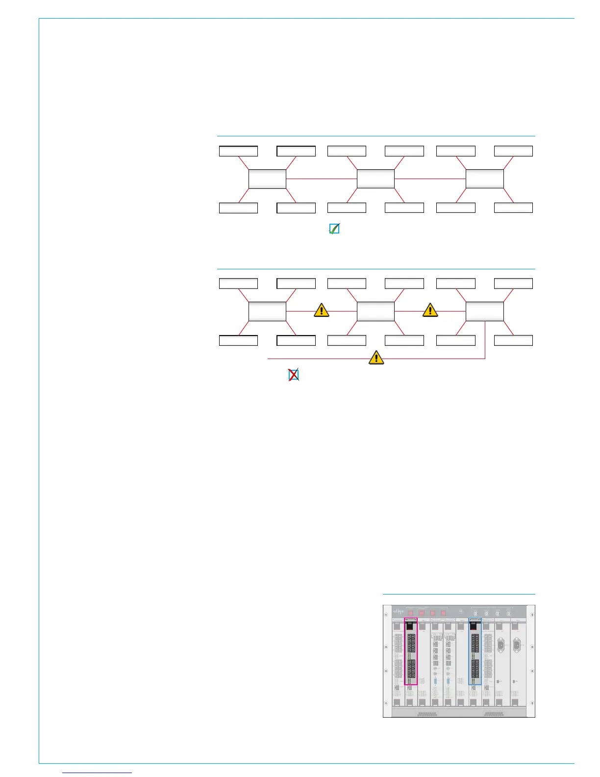
FIGURE 1 - CORRECT CONNECTION OF A THREE CONSOLE NETWORK
FIGURE 2 - INCORRECT CONNECTION OF A THREE CONSOLE NETWORK
Three router cores connected with no duplicate paths.
Incorrect connection! The additional link creates a duplicate path.
The path between I/O port and console
router may pass through other routers.
Figure 2 shows an incorrectly connected
network - the addition of a third router to
router links creates a duplicate path. This
will cause network collisions as data can
take two paths between any two routers -
one path is direct, the other is via the third
router. Removing any one of the router
to router links corrects this, effectively
changing the topology to match that in
Figure 1.
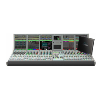
Figure 3 shows the 16 full bandwidth
router ports available on both the primary
and secondary main routers (as oppose
to expansion routers). Any of the 16
ports can be used to connect to another
Hydra2 router. Connections should
always be made from primary router to
primary router. To provide redundancy, a
backup connection should be made from
secondary router to secondary router.
When multiple cores are networked, it
is essential that they are all receiving
and are locked to the same derived sync
source.
CONTROL
ROUTER / EXPANDER
ENABLEDSPSYSTEM
RESETS
FAIL
GOOD
FANS
AES 3 VIDEO 2
VIDEO 1
WORD
CLOCK
SYNC INPUTS
DSP 1 PROCESSOR 1 PROCESSOR 2 DSP 2 PSU 1 PSU 2
CONTROL
EXPANSION 1 ROUTER 1 EXPANSION 2ROUTER 2
POK ST0
ST1 ST2
ST3 ST4
ST5 ST6
AC IN
USB
ST1 ST2
ST3 ST4
ST5 ST6
AC IN
USB
POK ST0
ROUTER / EXPANDER PSU PSUROUTER / EXPANDER ROUTER / EXPANDER
DSPDSP
ROUTER / EXPANDER
POK MA
PRI RST
MOK NOK
ST1 ST2
POK MA
PRI RST
MOK NOK
ST1 ST2
POK MA
PRI RST
MOK NOK
ST1 ST2
POK MA
PRI RST
MOK NOK
ST1 ST2
POK MA
PRI RST
MOK NOK
ST1 ST2
POK MA
PRI RST
MOK NOK
ST1 ST2
D1D2
D3
D4
D5
D6
D7
D8
D1D2
D3
D4
D5
D6
D7
D8
9
11
13
15
10
12
14
16
1
3
5
7
2
4
6
8
10 9
12 11
14
13
16 15
2 1
4
3
6
5
8
7
ETHERNET
LINKS
LINKS
9
11
13
15
10
12
14
16
1
3
5
7
2
4
6
8
10 9
12 11
14
13
16 15
2 1
4
3
6
5
8
7
ETHERNET
LINKS
LINKS
9
11
13
15
10
12
14
16
1
3
5
7
2
4
6
8
10 9
12 11
14
13
16 15
2 1
4
3
6
5
8
7
ETHERNET
LINKS
LINKS
9
11
13
15
10
12
14
16
1
3
5
7
2
4
6
8
10 9
12 11
14
13
16 15
2 1
4
3
6
5
8
7
ETHERNET
LINKS
LINKS
CONTROL PROCESSOR
MAC 6
MAC
4
MAC
3
MAC
5
USB
1
MOUSE
KBD
VGA
D1D0
R1R0
E1E0
MAPOK
RSTPRI
NOKMOK
ST2ST1
LOW BATTCF
USB
2
MAC 7
CONTROL PROCESSOR
MAC 6
MAC
4
MAC
3
MAC
5
USB
1
MOUSE
KBD
VGA
D1D0
R1R0
E1E0
MAPOK
RSTPRI
NOKMOK
ST2ST1
LOW BATTCF
USB
2
MAC 7
FIGURE 3 - MAIN ROUTER PORTS
From software version 1.16 onwards
Auto Promote can be used to specify
which routers in a Hydra2 network can
automatically take over the master router
status in the very unlikely event of a
master router failure. Please contact
Customer Support for guidance on
configuring auto-promoting routers. See
the Master Router section of the Hydra2
installation manual for more information.
Please refer to the Hydra2 installation
manual and H20 user guide for more
information regarding Hydra2 and I/O.
Router /
Processing
Core
Audio I/O Audio I/O
Audio I/OAudio I/O
Router /
Processing
Core
Audio I/O Audio I/O
Audio I/OAudio I/O
Router /
Processing
Core
Audio I/O Audio I/O
Audio I/OAudio I/O