Camus ProtoNode Start-up Guide
Page 27 of 87
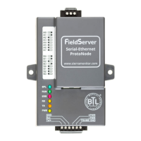
4.7 Serial Network (FPC-N34): Wiring Field Port to RS-485 Network
• Connect the RS-485 network wires to the 3-pin RS-485 connector on ProtoNode as shown below
in Figure 13.
o Use standard grounding principles for RS-485 GND
• See Section 5.5 for information on connecting to an Ethernet network.
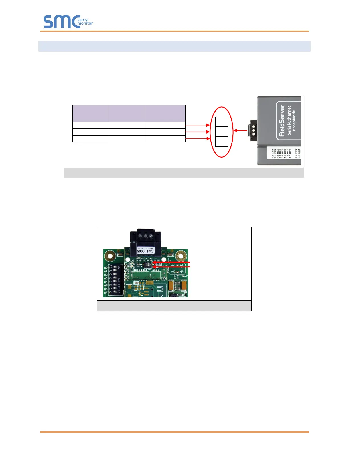
• If the ProtoNode is the last device on the trunk, then the end of line (EOL) termination switch needs
to be enabled. See Figure 14 for the orientation of switch positions referenced below.
o The default setting from the factory is OFF (switch position = right side)
o To enable the EOL termination, turn the EOL switch ON (switch position = left side)
• If more than one RS-485 device is connected to the network, then the field bias resistor switch
needs to be enabled to ensure proper communication. See Figure 14 for the orientation of switch
positions referenced below.
o The default factory setting is OFF (switch position = right side)
o To enable biasing, turn the bias switch ON (switch position = left side)
NOTE: Biasing only needs to be enabled on one device. The ProtoNode has 510 ohm resistors
that are used to set the biasing.
BMS
Wiring
ProtoNode
Pin #
Pin
Assignment
Figure 14: RS-485 EOL & Bias Resistor Switches
Figure 13: Connection from ProtoNode to RS-485 Field Network
 Loading...