Installing the RTU Open
RTU Open v3 CARRIER CORPORATION ©2019
Installation and Start-up Guide All rights reserved
14
Wire and
Terminal
Numbers
2-10 Vdc
- 1 & 2
- 4
- 5
- 6
- 7
- 8
- 7 & 8
Speed Fan / Y3
- 5 & 6
- Analog Input
- Analog Output
- Digital Input
- Digital Output
- 24 Vac required at this wire to provide
status. Provide a jumper from
- 1 to
- 9
if no safeties are used. See To wire inputs and outputs (page
16) for additional information on the RTU Open wiring harness
assembly terminations.
Parallel screw terminal at J5 (J5 - 1 = J2 - 6, J5 - 3 = J1 - 10, J5 - 5 = J1 - 2) may be used in place of the associated flying
leads at the harness (Part# OPN-RTUHRN). See To wire inputs and outputs (page 16) for additional information.
Binary Input 9: Integrated Gas Control reports status and if the flame is present.
1
N.C. contact must be used as a primary safety device for approved fire shutdown operation. N.O. contact for monitoring only.
2
If a function other the default is used, do NOT connect wires from J1-x.
Input wiring specifications
Thermistor 1000 feet
(305 meters)
22 AWG Unshielded
4-20 mA 3000 feet
(914 meters)
22 AWG Unshielded
Binary input
1000 feet
(305 meters)
22 AWG Unshielded
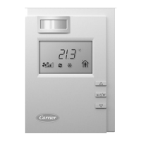
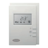
ZS sensors
Wireless Adapter for
wireless sensors
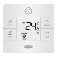
Equipment Touch
TruVu™ ET Display
See Wiring devices to the RTU Open's Rnet port (page 22).
 Loading...
