Installing the RTU Open
RTU Open v3 CARRIER CORPORATION ©2019
Installation and Start-up Guide All rights reserved
18
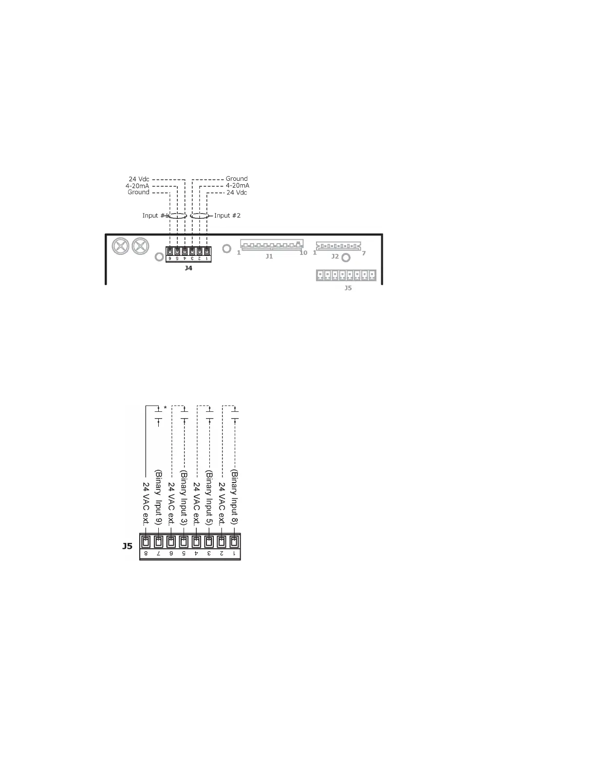
J4 Inputs
1 Turn
the RTU Open's power.
2 Connect the input and output wiring to the screw terminals on the RTU Open.
When utilizing the controller's 24 Vdc auxiliary power out, the total current demand for these two input
channels must not exceed 40 mA (or a maximum of 25 mA per channel).
Analog Inputs 1 and 2 may be set for the following device types:
• IAQ Sensor
• OAQ Sensor
• Space RH Sensor
J5 Inputs
The terminals for Inputs 3, 5, and 8 are available for use in place of the flying wire leads at Molex connectors J1
and J2 identified below:
binary inputs 3, 5, and 8 are the same input channels as:
•
wire
2,
Input - 3 (
)
•
wire
10,
Input - 5 (
)
•
wire 6,
-
Input - 8 (
).