Overview of Screens Chore-Tronics® 2 Control
50
MT1843B
(Setup-General Screen) Outputs Tab
To access the Setup-General "Outputs Screen", press the Tab Key under "Outputs".
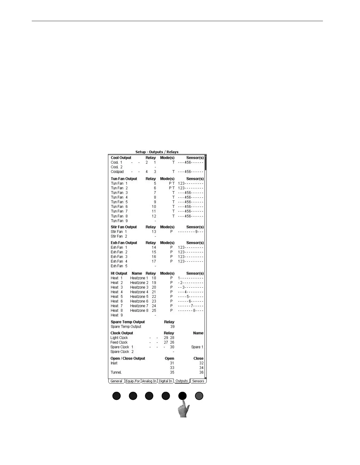
Every desired output needs to have a relay assigned to it, a mode of operation (Power,
Natural, Tunnel, or combinations of the three) and temperature sensor(s) assigned to
it. For the Cool, Exhaust Fan, Stir Fan, Tunnel Fan and Heat Zone only one output
will appear in the list at initial setup. As an output is assigned to a relay, the next
output number in list will appear. For example, Tunnel Fan 1 is wired to relay #5,
operating in both power and tunnel modes and is being controlled by the average
temperature of sensors 1,2, and 3. Scroll through the output names to the Tun Fan
output section. Tun Fan 1 will be the only tunnel fan output visible. Under the relay
column enter relay #5, under the Mode column edit the line to read P T, and the
Sensor Column enter sensors 1, 2, and 3. The Tun Fan 2 output should now appear.
Continue assigning relays until all desired outputs have had a relay assigned to them.
Verify the relay assignments with the Output Stickers on the Manual Toggle
Switches.
MT1842-042 10/04
Figure 63. Setup-General Screen: Outputs Tab