Chore-Tronics® 2 Control Overview of Screens
MT1843B
55
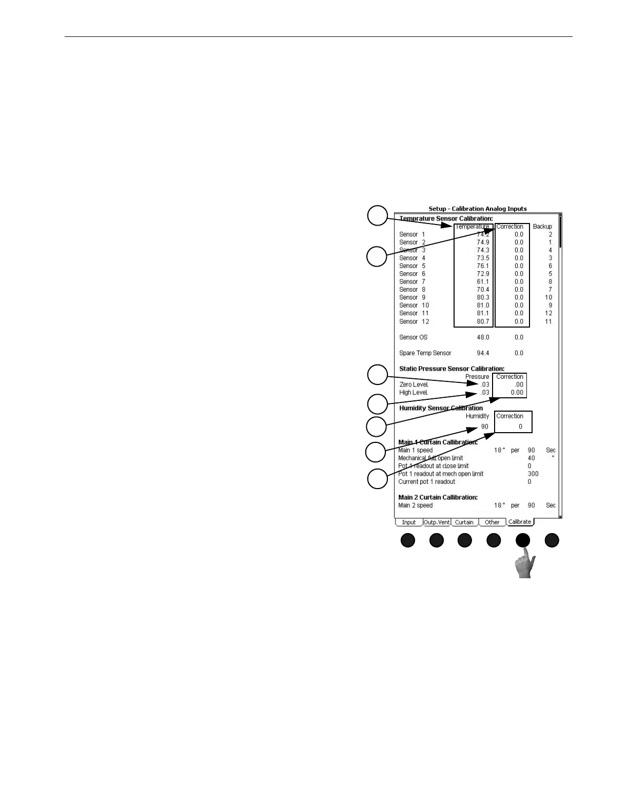
(Setup-Control Screen) Calibrate Analog Inputs Tab
To access the Setup-Control "Calibrate Analog Inputs Tab", press the Tab Key below "Calibrate". This
screen allows the user to assign backup temperature sensors and to re-calibrate Inputs if necessary. It is
strongly recommended that every sensor have a backup assigned to it. This backup sensor will take over
operation if the primary sensor fails. It is recommended that the backup sensor be in the same general area
as the primary sensor. As a default, every sensor is backed up by the next sensor below it. For example,
sensor 6 is backed up by sensor 5.
The re-calibration section of this screen should not need to be used at initial installation and start-up of
the Control unless natural ventilation is used. If natural ventilation is being used then the potentiometers
will need to be calibrated at this time. If it is felt that one of the Inputs needs to be re-calibrated perform
the following steps…
Relative Humidity Sensor
To re calibrate the Relative Humidity Sensor first obtain a sling psychrometer or other humidity-
measuring device. Operate the psychrometer in the same area that the Relative Humidity Sensor is
installed. Take the reading on the psychrometer and compare it to the reading on the Setup-Control
"Calibration" Screen (Figure 69, above). If the readings do not match, then change the reading under the
Humidity column, (Item 6), to match the reading of the psychrometer. The correction column, (Item 7),
is to be used for service information and for returning to factory settings only.
MT1842-083 10/04
1
Figure 69. Setup-Control Screen:
Calibrate Tab
Temperature Sensors
To re-calibrate the Temperature Sensors, first obtain a
digital thermometer that has a readout of at least .1°. Do not
use a temperature gun. A temperature gun takes object
temperatures, not air temperatures. Place the digital
thermometer next to the Temperature Sensor that is being
re-calibrated. Take the reading from the digital thermometer
and enter that number under the temperature column, (Item 1
Figure 69), of the Sensor being calibrated. The Correction
column, (Item 2), is used only for service information and to
return the Control to the factory settings. The settings should
be reset to factory whenever a re-calibrated Temperature
Sensor is replaced. To return to factory settings change the
number under the correction column by one digit.This will
cause the correction to automatically zero out and return to
factory setting.
Static Pressure Sensor
To re-calibrate the Static Pressure Sensor first obtain a
manometer or other static pressure measuring device. Then
disconnect both hoses from the Static Pressure Sensor.
Go to the static pressure portion of the screen and look
at the Pressure reading on the Zero Level line (Item 3).
If the reading is not zero then change the zero level
pressure to read zero. The zero level has now been calibrated.
To calibrate the high level, first make sure that the Manometer
has been installed in the house and reconnect the hoses to the
Static Pressure Sensor. Open the Inlets slightly and turn on
enough Fans to create a static pressure of at least 0.15 inches
of w.c. at the Manometer. Compare the Manometer reading to
the reading on the High Level line on the Control (Item 4). If
the readings do not match, edit the pressure reading on the
High Level line to match the reading of the Manometer. As
with the Temperature Sensors, the Correction column, (Item
5), of the static pressure calibration is used for service, and to
return the Control to factory settings only. This completes the
re-calibration of the static pressure Sensor.
1
2
3
4
5
6
7