Control Installation Chore-Tronics® 2 Control
72
MT1843B
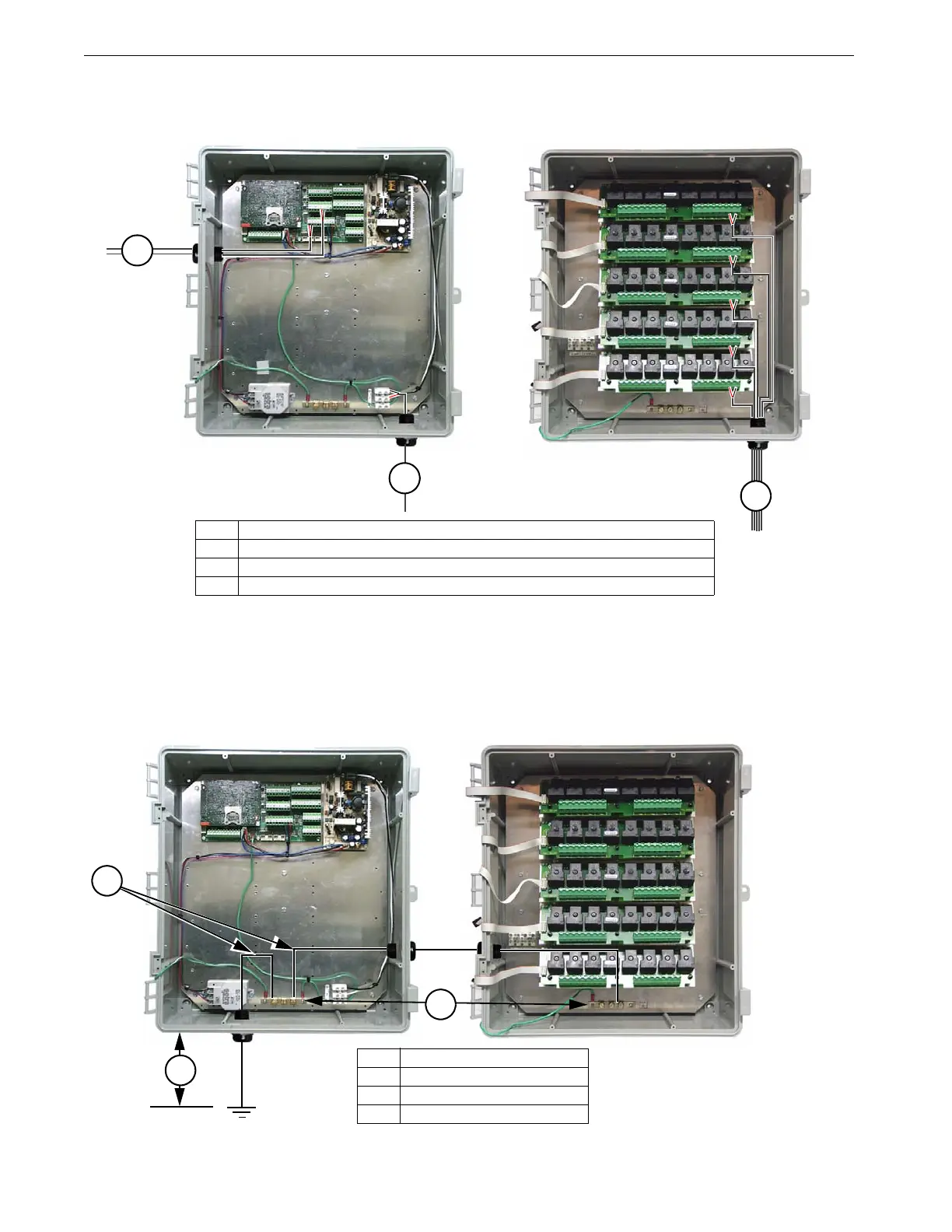
When wiring the Control it is recommended that the line voltage wires be brought into the bottom of the
Boxes and the low voltage wires (Temperature Sensors, Potentiometers, relative humidity, etc.) be
brought in the side of the Control Box (See Figure 79).
When grounding the Control, connect only the Ground Rail of the Main Box to the Earth ground. Connect
the Ground Rail from the Main Box to the Ground Rail of the Relay Box. It is recommended that a ground
rod be located no more than 8’[2.438 m] to 10’ [3.048 m] away from the Control. The Chore-Tronics
®
2
Control should be connected to ground using a 12 gauge wire or larger. As always, check the local electric
code for additional requirements.
Figure 79. Low Voltage Wire Routing
Item Description
1 Temperature Sensor, Potentiometer, relative humidity wires etc. (Low Voltage)
2 Line Voltage Wires
3 Input/Output wires (High Voltage)
3
2
1
Figure 80. Ground Wire Routing
Item Description
1 Ground Rails
2 Ground Wires
3 8’-10’[2.438 m-3.048 m] Max.
Earth Ground
3
2
1