Programmable DC Electronic Load 63600 Series Operation & Programming Manual
d. 5.0V: It sets the Dout High level to 5.0V.
8. DGNDC: Digital signal reference ground.
9. EXT_WAVE [1:10]: External wave input signals from the first channel
to the tenth channel, the input range is from 0 to 10V.
10. VMON [1:10]: Voltage monitor output signals from the first channel to
the tenth channel, the output range is from 0 to 10V.
11. IMON [1:10]: Current monitor output signals from the first channel to
the tenth channel, the output range is from 0 to 10V.
12. AGNDC: Analog signal reference ground.
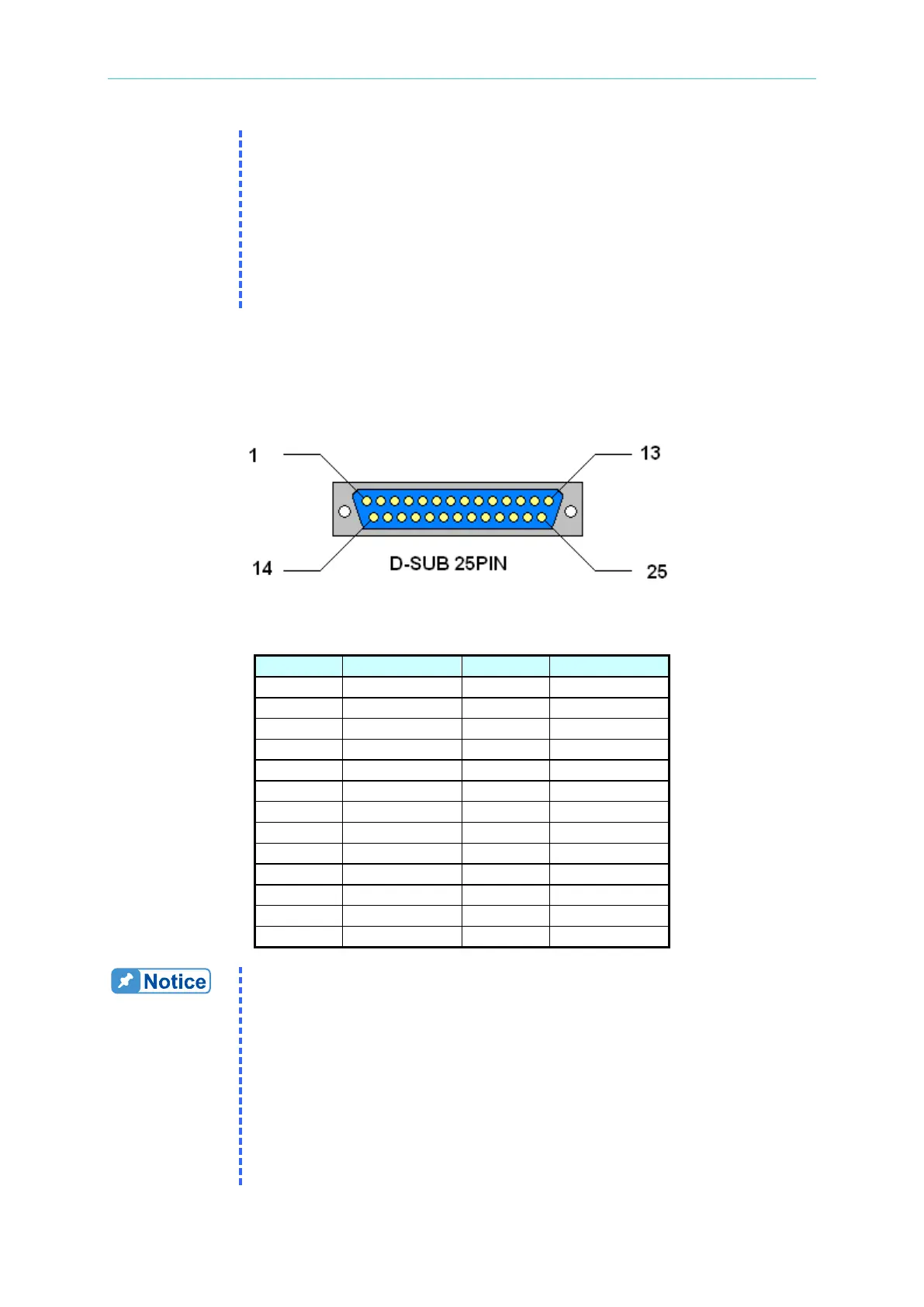
The System I/O port on the 63600-2 Mainframe rear panel is a 25-pin connector (D-SUB
25pin male connector). It includes Analog signals: voltage and current monitor and external
wave input, and Digital System I/O signals. The Digital System I/O signals are TTL
Compatible. They are defined as follows.
Figure 4-11 63600-2 System I/O Port Connector
Table 4-9 63600-2 Pin Assignments of the System I/O Port Connector
1. TTL High Level Voltage is 5V
。
2. SHORT [1:4]: Short ON output signals from the first channel to the
fourth channel, TTL Level, Active High.
3. TRIG_ SEQ: External trigger input signal to get to the next
sequence automatically. TTL Level, falling edge, pulse width≥1μs.
4. TRIG_DIGI: External trigger input signal to be the trigger Source of
Digitizing Function. TTL Level, falling edge, pulse width ≥1μs.
5. LOAD_ON: Load ON output signal, TTL Level, Active High.
6. DI [1:2]: 2 bits of digital input signals, TTL Compatible.
DI1 and DI2 have External Load ON/OFF function. The user can
use this input signal to control the Load ON/OFF externally. If DI1
 Loading...