Programmable DC Electronic Load 63600 Series Operation & Programming Manual
When the power is set to 400W, the power specification range is shown as follows:
DMM (W) maximum value: 400 + (0.3%×400 + 0.3%×6400) = 420.4W
DMM (W) minimum value: 400 - (0.3%×400 + 0.3%×6400) = 379.6W
Panel power reading range: DMM(W)±(0.1%×400 + 0.1%×6400)= DMM(W)±6.8W
7.3.4.1 Checking High Power Range
A. Connect the load module, DC Source, DMM and Current Shunt as Figure 7-1 shows.
Use DMM (W) to measure the voltage passing through the module’s input terminal. Be
careful in making connections so that contact resistance voltage drop will not affect the
readings.
B. Press till VFD shows CP press to light up the H range LED indicator.
C. Press to set load voltage and press to set limit current. The DC Source
voltage output and limit current settings are based on the voltage/current values listed in
Table 7-14.
D. Next, press to enable the load and wait for 30 seconds to record the voltage
passing through the negative input terminal.
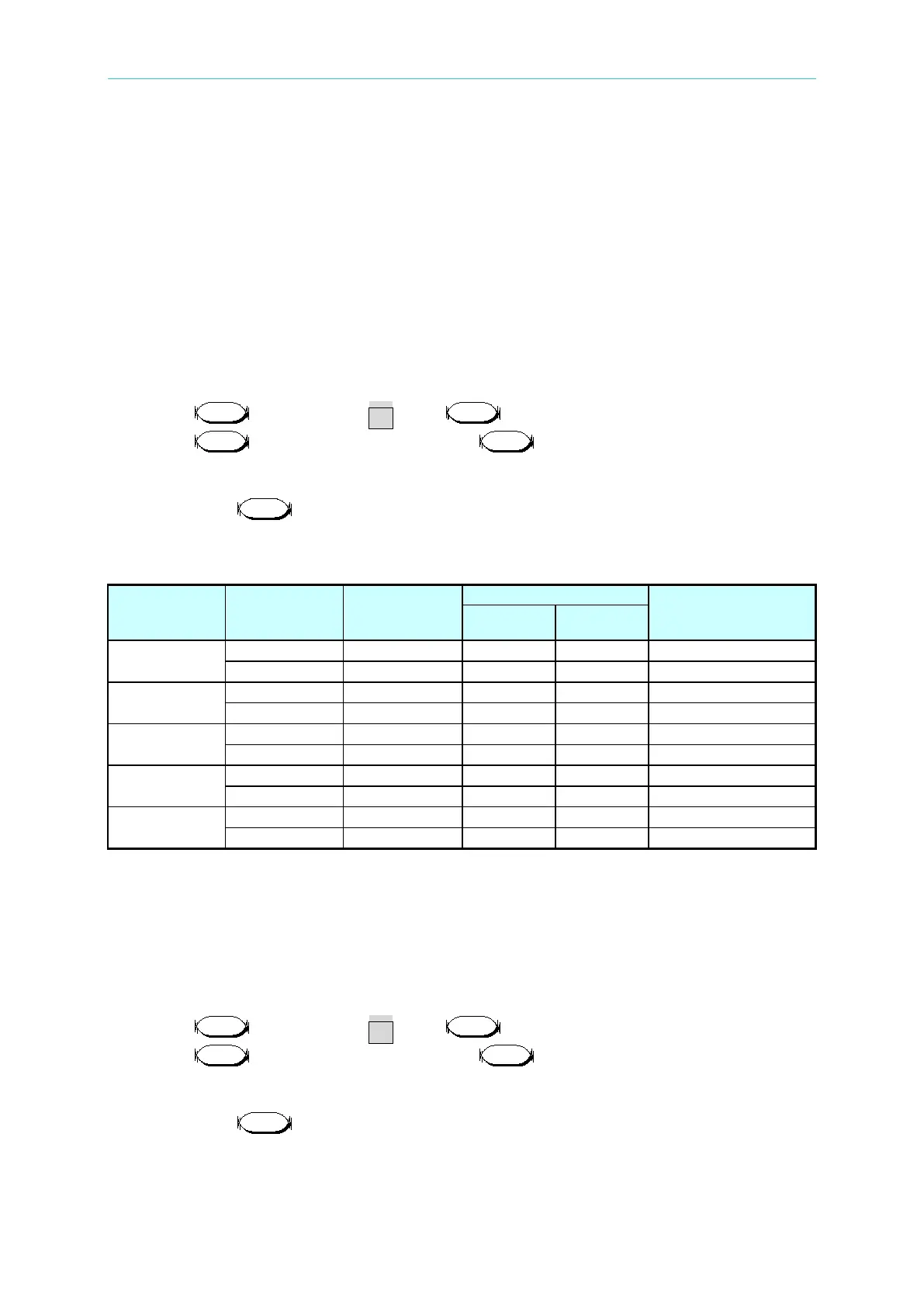
Table 7-14
Model
Load Power
Setting
Voltage/ Limit
Front Panel Display
Reading (W)
Max. Min.
63630-600-15
63640-150-60
63630-80-60
63610-80-20
63640-80-80
7.3.4.2 Checking Medium Power Range
A. Connect the load module, DC Source, DMM and Current Shunt as Figure 7-1 shows.
Use DMM (W) to measure the voltage passing through the module’s input terminal. Be
careful in making connections so that contact resistance voltage drop will not affect the
readings.
B. Press till VFD shows CP press to light up the M range LED indicator.
C. Press to set load voltage and press to set limit current. The DC Source
voltage output and limit current settings are based on the voltage/current values listed in
Table 7-15.
D. Next, press to enable the load and wait for 30 seconds to record the voltage
passing through the negative input terminal.
 Loading...

