Programmable DC Electronic Load 63600 Series Operation & Programming Manual
4.11 Universal Serial Bus (USB) Port
The Universal Serial Bus (USB) Port on the Mainframe rear panel is a 4-pin USB connector.
It is available for USB connecting to a remote controller or a personal computer for remote
control. The Universal Serial Bus (USB) signal is defined as follows.
Table 4-6 Universal Serial Bus (USB) Connector
4.12 System Bus Port
The parameter of System Bus is set in the configuration remote. Please refer to 4.7.1.
There are two System Bus ports on the Mainframe rear panel. They are 10-pin connectors
(RJ-45, male connector). The System Bus connector bus signal is defined as follows.
Table 4-7 System Bus Connector
When in Synchronous Dynamic Mode, the SYNCW will change by T1/T2. When
in T1 the SYNCW output is High and when in T2 the SYNCW output is Low.
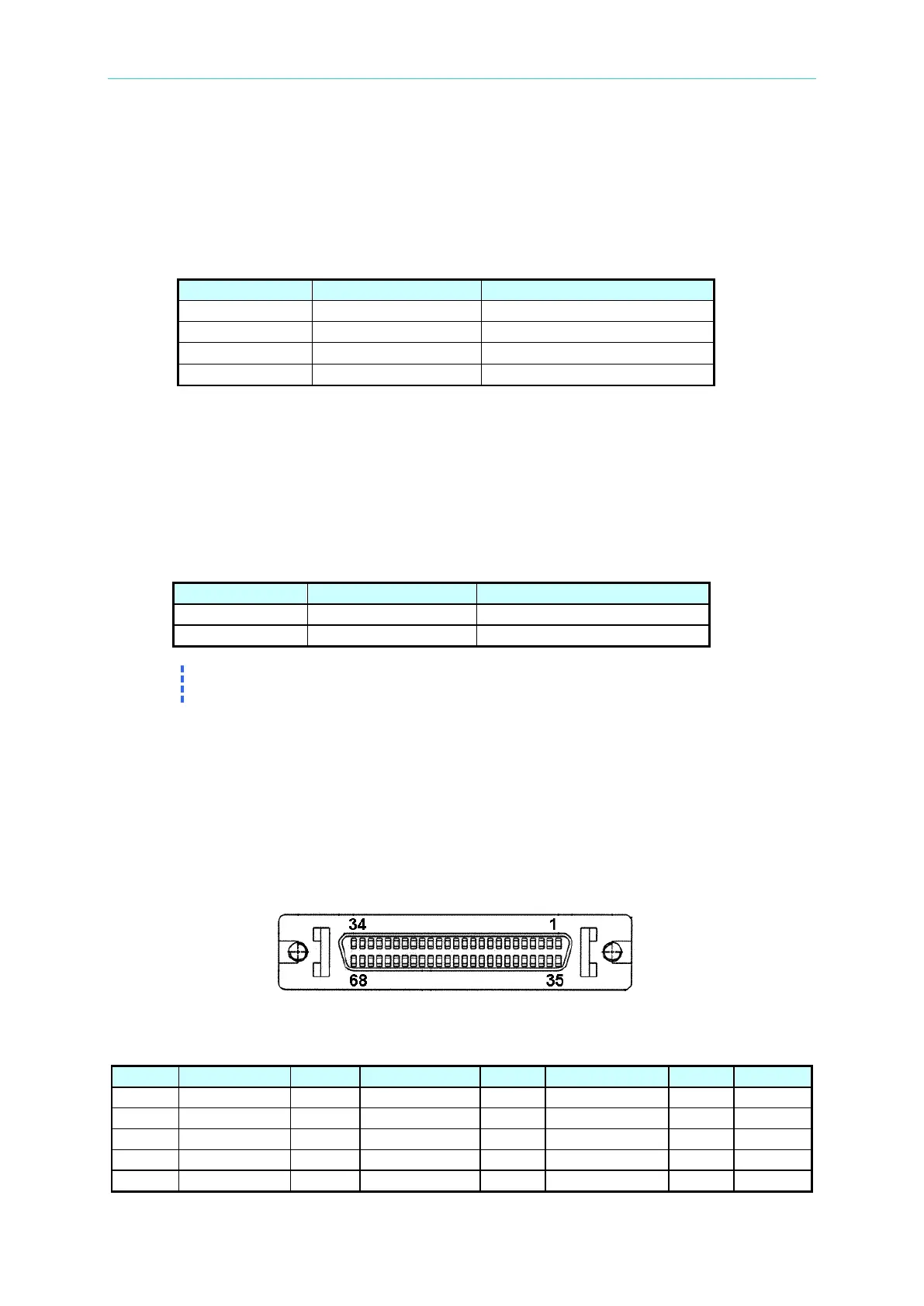
4.13 Connecting the System I/O Port
The System I/O port on the rear panel of the 63600-5 mainframe is a 68-pin connector (SCSI
68 pins, female connector). It includes 0-10VDC analog signals: voltage and current monitor,
external analog signal input and digital I/O signals. The digital system I/O signals are TTL
compatible. Definitions as follows:
Figure 4-10 63600-5 System I/O Port Connector
Table 4-8 Pin Assignments of 63600-5 System I/O Port Connector
 Loading...

