Programmable DC Electronic Load 63600 Series Operation & Programming Manual
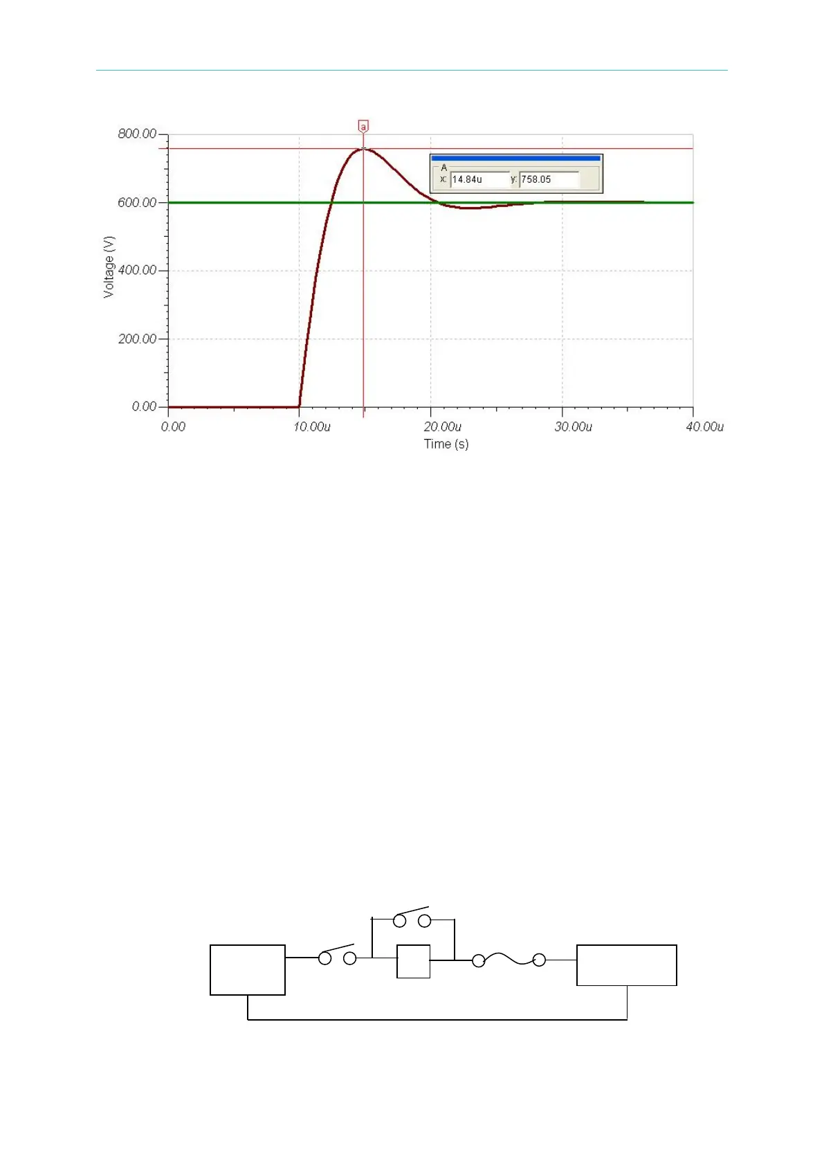
Figure A-2
Simulation of Surge Chart when Switching between Electronic Load & Battery
During the test procedure if the entire circuit is shorted due to MOSFET breakdown by high
voltage and if the energy source is battery or other source that can provide high power,
continuous high current will pass through Electronic Load internal due to short circuit. The
load and the battery should be disconnected immediately. If unable to do so, the huge
energy of battery output may cause the Electronic Load to burnout or even more severe
situation. To prevent this from happening, a mechanism of over current protection is required.
For the above situation, it is suggested not to connect the battery and Electronic Load
directly using a switch only to avoid damaging the equipment.
A.1 Measures for Improvement
A.1.1 Additional Protection Switch
As the burnout may expand due to the MOSFET damage and continuous energy release
from battery that caused by the conditions described previously, it is suggested to connect
the wires as Figure A-3 shows below when doing the battery charge/discharge tests to
prevent problems from happening and to ensure the safety of using Electronic Load.
Figure A-3 Wire Connecting Diagram of LOAD & Battery
NFB(No-Fuse Breaker): The capacity (current amount) should be smaller than maximum
 Loading...

