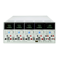
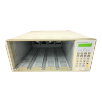
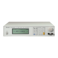
Programmable DC Electronic Load 63600 Series Operation & Programming Manual
5.1.4.4 Communicating with Instruments ....................................................... 5-11
5.2 Introduction to Programming ............................................................................. 5-16
5.2.1 Basic Definition ......................................................................................... 5-16
5.2.2 Numerical Data Formats............................................................................ 5-17
5.2.3 Character Data Formats ............................................................................ 5-18
5.2.4 Arbitrary Block Data Format ...................................................................... 5-18
5.2.5 Separators and Terminators ...................................................................... 5-19
5.3 Language Dictionary ......................................................................................... 5-20
5.3.1 Common Commands ................................................................................ 5-20
5.3.2 Specific Commands .................................................................................. 5-24
5.3.2.1 ABORT Subsystem ........................................................................... 5-24
5.3.2.2 ADVANCE Subsystem ....................................................................... 5-25
5.3.2.3 CHANNEL Subsystem ....................................................................... 5-37
5.3.2.4 CONFIGURE Subsystem .................................................................. 5-39
5.3.2.5 CURRENT Subsystem ...................................................................... 5-47
5.3.2.6 DIGITIZING Subsystem ..................................................................... 5-55
5.3.2.7 FETCH Subsystem ............................................................................ 5-59
5.3.2.8 IMPEDANCE Subsystem ................................................................... 5-63
5.3.2.9 LOAD Subsystem .............................................................................. 5-65
5.3.2.10 MEASURE Subsystem ...................................................................... 5-67
5.3.2.11 MODE Subsystem ............................................................................. 5-69
5.3.2.12 POWER Subsystem .......................................................................... 5-70
5.3.2.13 PROGRAM Subsystem ..................................................................... 5-72
5.3.2.14 RESISTANCE Subsystem ................................................................. 5-78
5.3.2.15 RUN Subsystem ................................................................................ 5-80
5.3.2.16 SHOW Subsystem ............................................................................. 5-80
5.3.2.17 SYNCHRONOUS Subsystem ............................................................ 5-81
5.3.2.18 SPECIFICATION Subsystem ............................................................. 5-82
5.3.2.19 STATUS Subsystem .......................................................................... 5-86
5.3.2.20 VOLTAGE Subsystem ....................................................................... 5-90
5.3.2.21 SYSTEM Subsystem ......................................................................... 5-92
6. Status Reporting ....................................................................................................... 6-1
6.1 Introduction ......................................................................................................... 6-1
6.2 Register Information in Common ......................................................................... 6-1
6.2.1 Channel Status ............................................................................................ 6-3
6.2.2 Channel Summary....................................................................................... 6-4
6.2.3 Questionable Status .................................................................................... 6-4
6.2.4 Output Queue .............................................................................................. 6-4
6.2.5 Standard Event Status ................................................................................ 6-5
6.2.6 Status Byte Register .................................................................................... 6-5
6.2.7 Service Request Enable Register ................................................................ 6-6
7. Verification ................................................................................................................ 7-1
7.1 Introduction ......................................................................................................... 7-1
7.2 Equipment Required ........................................................................................... 7-1
7.3 Performance Tests .............................................................................................. 7-1
7.3.1 CC Mode Verification .................................................................................. 7-1
7.3.1.1 Checking High Current Range ............................................................. 7-2
7.3.1.2 Checking Medium Current Range ........................................................ 7-3
7.3.1.3 Checking Low Current Range .............................................................. 7-4
7.3.2 CR Mode Verification .................................................................................. 7-5
7.3.2.1 Checking High ohm Range .................................................................. 7-5
7.3.2.2 Checking Medium ohm Range ............................................................. 7-6
7.3.2.3 Checking Low ohm Range .................................................................. 7-7
 Loading...


