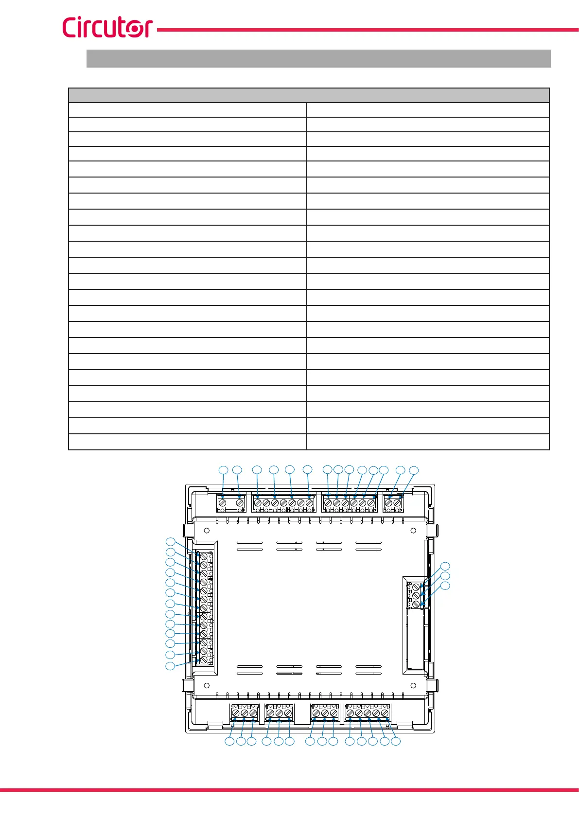
3.4.- DEVICE TERMINALS
Table 3:List of Computer SMART III terminals
Terminals of the top side of the device
1: A1,
Auxiliary power supply. 23: R8, Relay output 8 (Computer SMART III 12 and 14 models)
2: A2,
Auxiliary power supply. 24: R9, Relay output 9 (Computer SMART III 12 and 14 models)
3: V
L1
, L1 voltage input 25: R10, Relay output 10 (Computer SMART III 12 and 14 models)
4: V
L2
, L2 voltage input 26: R11, Relay output 11 (Computer SMART III 12 and 14 models)
5: V
L3
,L3 voltage input
27: R12, Relay output 12 (Computer SMART III 12 and 14 models)
6: V
LN,
Neutral voltage input
28: A(+), RS-485
7: S1,
L1 current input
29: B(-), RS-485
8: S2, L1 current input
30: S, GND for RS-485
9: S1,
L2 current input
31: 1, Digital input 1
10: S2, L2 current input
32: 1, Digital input 2
11: S1,
L3 current input
33: C, Common to the digital inputs
12: S2, L3 current input
34: 1, Digital output 1
13: S1,
Leakage current input
35: 2, Digital output 2
14: S2, Leakage current input
36: C, Common to the digital outputs
15: COM, Common relays
37: Fan relay output
16: R1, Relay output 1
38: Fan relay output
17: R2, Relay output 2
39: NC, Alarm relay output
18: R3, Relay output 3
40: C, Alarm relay output
19: R4, Relay output 4
41: NO, Alarm relay output
20: R5, Relay output 5
42: COM, Common relays
21: R6, Relay output 6
43: R12, Relay output 13 (Computer SMART III 14 model)
22: R7, Relay output 7 (Computer SMART III 12 and 14 models)
44: R12, Relay output 14 (Computer SMART III 14 model)
3
2
1
4
5 6
7 8 9 10 11 12 13
15
14
16
17
18
19
20
21
22
23
24
25
26
27
28 29 30 31 32 33 34 35 36 37 38 39 40 41
42
43
44
Figure 2: Computer SMART III terminals.
12
Computer SMART III
Instruction Manual