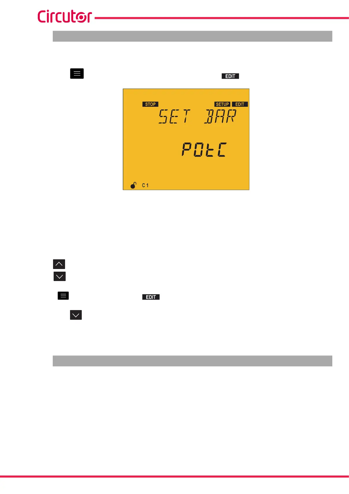
5.16.- ANALOGUE BAR
In this point the parameter to be displayed in the analogue bar (“4.4.3. ANALOGUE BAR”) can be
configured.
Press the key to enter edit mode. It is identified by the symbol and the flashing of the
digits to be modified.
The following display options are available for the analogue bar:
POTC: the percentage of power connected to the capacitor bank relative to the total power.
THdI: the Current THD of each phase.
I: the current % of each one of the phases.
nO: no parameters are displayed.
The key shows the next option.
The key shows the previous option.
Press to validate the data; the symbol disappears from the display.
Press the key to access the next programming step.
If no keys are pressed for 5 minutes, the device switches to the simulation screen, “5.30.- SIMULATION
SCREEN”.
5.17.- FAN
In this point the activation of the relay output associated with the fan can be configured.
It is possible to configure whether or it is enabled ON or not OFF, as well as the temperature above
which it is to be activated or deactivated.
The device has a hysteresis value of 5ºC when disconnecting the fan, in order to avoid continuous
connections and disconnections.
90
Computer SMART III
Instruction Manual