3.5.- CONNECTION DIAGRAM
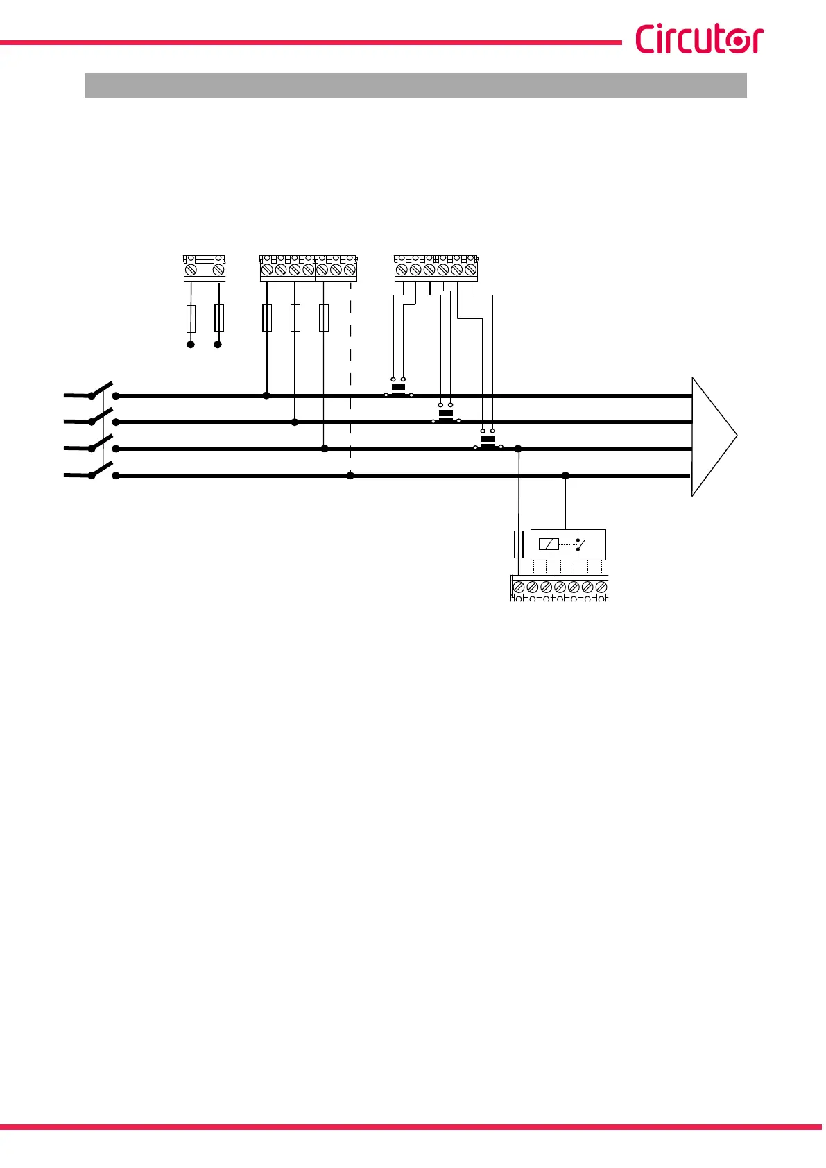
3.5.1.- 3 voltages + neutral and 3 currents, Computer SMART III 6 model
Connection type: 3U.3C
VLN
IL2
S1
L1
L2
L3
N
VL1 VL2 VL3
S1 S2
P1
P2
S1 S2
P1
P2
S1 S2
P1
P2
S1 S1S2 S2 S2
IL3
IL1
A B
Power
Supply
COM 1 2 3 4 5 6
Relay
Power
Supply
Figure 3: 3 voltages + neutral and 3 currents, Computer SMART III 6 model.
Note: If the connection layout mentioned above is not respected, the phase must be adjusted, following
the procedure described in section “5.6.- PHASE CONNECTION”
Note: In this type of connection, the connection from Neutral to V
LN
is not mandatory.
13
Instruction Manual
Computer SMART III