4.7.- INPUTS
The Computer SMART III comprises two digital inputs (terminals 31 and 32 of Figure 2) for activating
any of the four target cos φ, in other words, the desired power factor for the installation, which can be
programmed in the device. See “5.3.- TARGET COS φ”
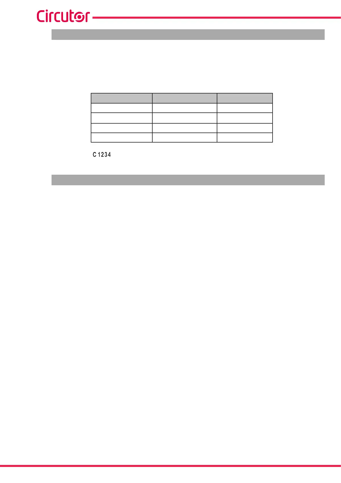
Table 11: Selection of the target cos φ.
Digital input 2 Digital Input 1
Target cos φ
0 0 1
0 1 2
1 0 3
1 1 4
On the display, the icon indicates which of the four possible target cosines was selected.
4.8.- OUTPUTS
The device features:
A relay (terminals 37 and 38 of Figure 2) dedicated to activating a fan when a pre-determined
temperature is exceeded, which can be programmed in “5.17.- FAN”, also connected to the Fan
LED.
A fully programmable alarm relay (terminals 39, 40 and 41 of Figure 2); see “5.21.- ENABLING
ALARMS”
Two digital outputs, optoisolated NPN transistors (terminals 34, 35 and 36 of Figure 2), fully
programmable; see “5.21.- ENABLING ALARMS”.
Computer SMART III 6 model:
Six output relays (terminals 15 to 21 of Figure 2) for regulating the cos φ by means of capac-
itors.
Computer SMART III 12 model:
Twelve output relays (terminals 15 to 27 of Figure 2) for regulating the cos φ by means of
capacitors.
Computer SMART III 14 model:
Fourteen output relays (terminals 15 to 27 and 42 to 44 of Figure 2) for regulating the cos φ
by means of capacitors.
58
Computer SMART III
Instruction Manual