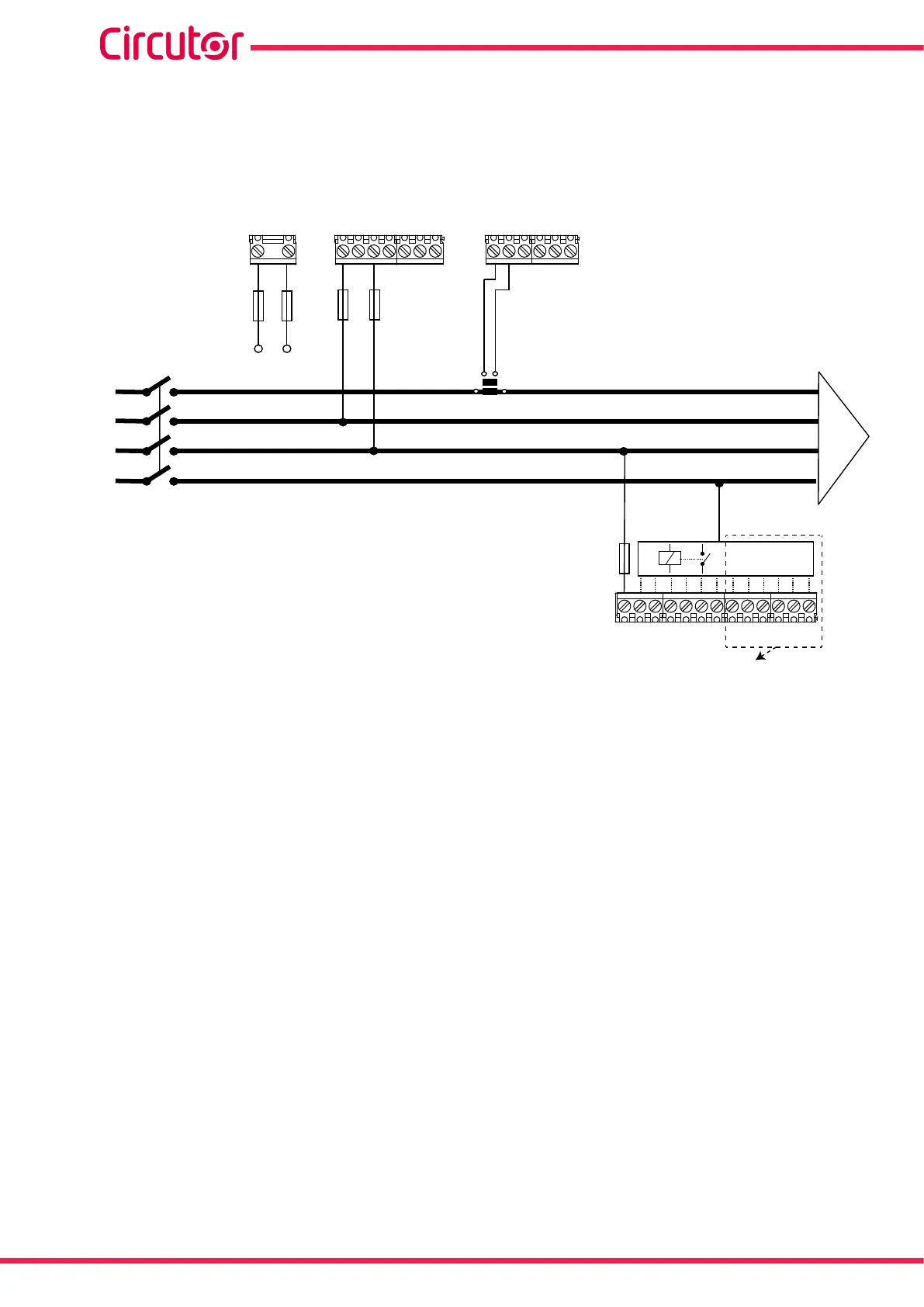
3.5.8.- 2 voltages and 1 current, Computer SMART III 12 model
Connection type: 2U.1C
VLN
IL2
S1
L1
L2
L3
N
VL1 VL2 VL3
S1 S2
P1
P2
S1 S1S2 S2 S2
IL3
IL1
A1 A2
Power Supply
COM 1 2 3 4 5 6 7 8 9 101112
Relay
For Computer SMART III 12
Power Supply
Figure 10: 2 voltages and 1 current, Computer SMART III 12 model.
Note: If the connection layout mentioned above is not respected, the phase must be adjusted, follow-
ing the procedure described in section “5.6.- PHASE CONNECTION”
Note: In this type of connection, the Neutral connection is not necessary.
Note: In this type of connection, the current transformer must be connected to the IL1 terminals, and
the two voltages must be connected to VL1 and VL2.
20
Computer SMART III
Instruction Manual