Press the key to enter edit mode. It is identified by the symbol and the flashing of the
digits to be modified.
The key shows the next option and the key shows the previous option.
Press to validate the data; the symbol disappears from the display.
Press the key to access the next programming step.
If no keys are pressed for 5 minutes, the device switches to the simulation screen, “5.30.- SIMULATION
SCREEN”.
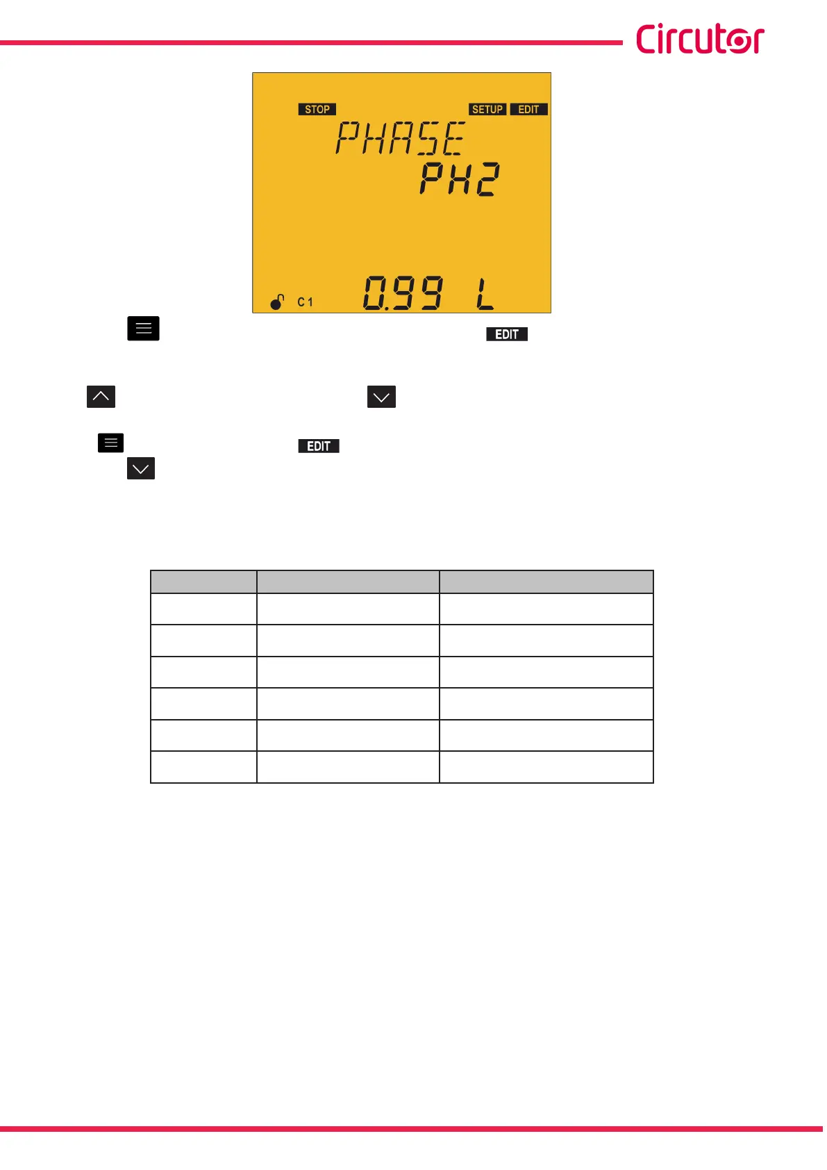
Table 42:Phase connection options.
Phases
V measurement phase CT connection phase
PH1
L1-L2-L3 L1
PH2
L1-L2-L3 L2
PH3
L1-L2-L3 L3
PH4
L1-L2-L3 L1 (inverted transformer)
PH5
L1-L2-L3 L2 (inverted transformer)
PH6
L1-L2-L3 L3 (inverted transformer)
Connection type 3u3C
If the connection with three currents has been selected (3u3C), each current is associated with its
voltage and the direction of the current is indicated in this screen.
d: direct.
i : reverse.
79
Instruction Manual
Computer SMART III