Press the key to enter edit mode. It is identified by the symbol and the flashing of the
digits to be modified.
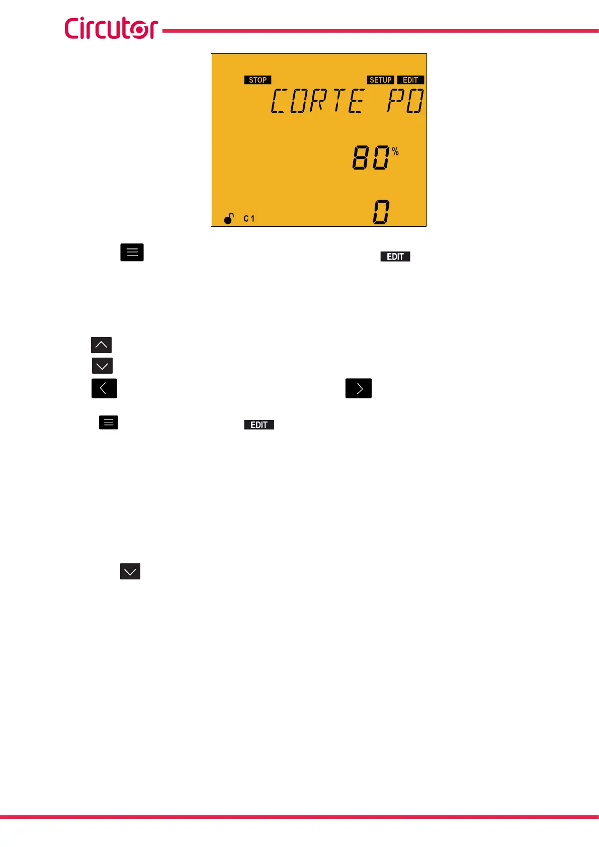
The voltage threshold is programmed as a percentage of the configured primary voltage’s value (“5.12.-
VOLTAGE TRANSFORMATION RATIO”).
The key increases the digit value or shows the next option.
The key reduces the digit value or shows the next option.
The key skips to the previous parameter and the key skips to the next parameter.
Press to validate the data; the symbol disappears from the display.
Maximum value: 0 %.
Minimum value: 100 %.
Note: If 0% is programmed, the functionality is disabled.
Note: The value displayed in the fourth row (0 in the image) is not editable and indicates the number
of times that the Undervoltage trip function has been activated. This value is reset each time the value
is reconfigured.
Press the key to access the next programming step.
If no keys are pressed for 5 minutes, the device switches to the simulation screen, “5.30.- SIMULATION
SCREEN”.
92
Computer SMART III
Instruction Manual