4-5
Cisco 7600 Series Router Installation Guide
OL-4503-26
Chapter 4 Troubleshooting
Troubleshooting Inadequate Power for all the Modules
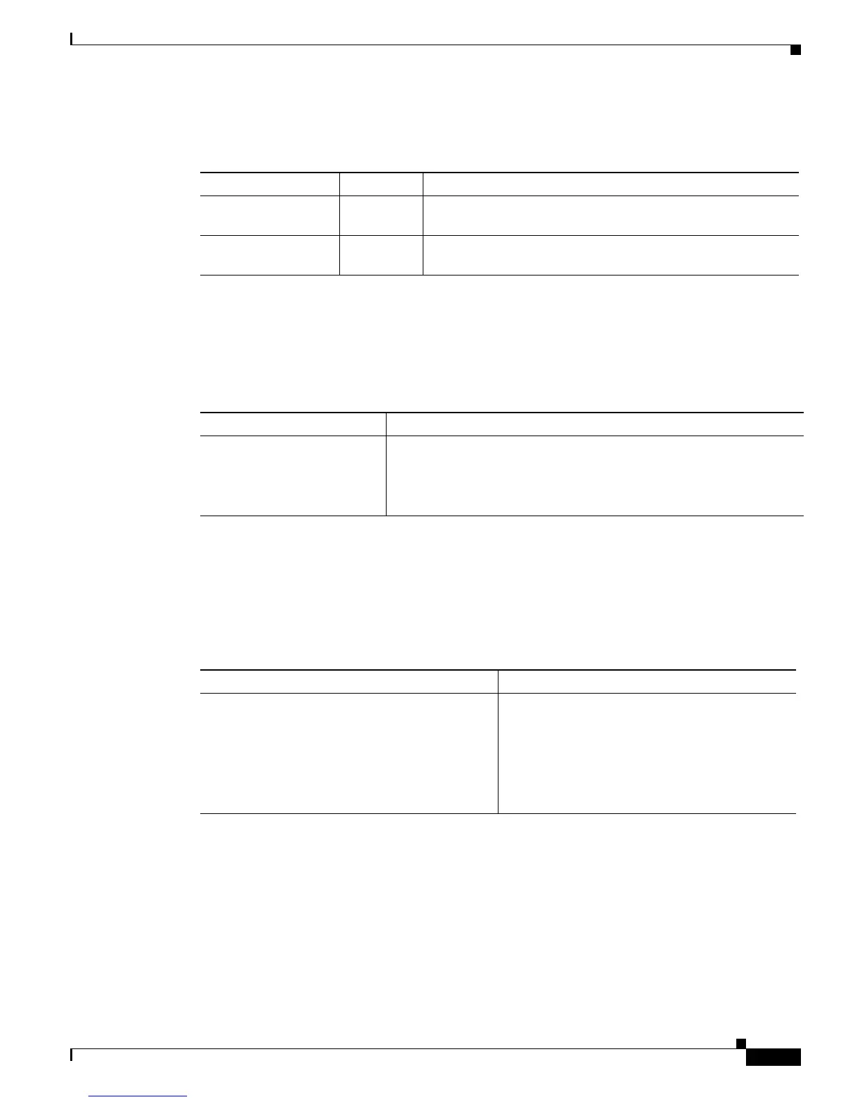
Table 4-2 maps the LED indicator information in a power supply sub-system.
Ta b l e 4-2 Power Supply Indicator Information
Troubleshooting Inadequate Power for all the Modules
If there is not enough power to initiate all the modules, follow the solutions listed in Table 4-3.
Troubleshooting Power Latch Up
When two power supplies are present in the system, they work in redundant mode where 50% of the
power is drawn from each power supply.
Table 4-4 lists the solutions for the power latch issues.
Ta b l e 4-4 Troubleshooting Power Latch Up Issues
Troubleshooting the Cooling Sub-System
The cooling system dissipates heat generated by the chassis and controls the temperature of chassis
components. The cooling system has a fully redundant architecture that allows the chassis to continue
operating with a single-fault failure (such as a single fan or fan tray failure).
The chassis cooling system includes:
• One or Two fan trays (depending upon the chassis).
Color Indicator Description
Green Power input Power is available; however if the LED is OFF, it indicates lack
of power.
Red Output fail Power is not available; however, if the LED is OFF, it indicates
the presence of the output power.
Ta b l e 4-3 Troubleshooting Inadequate Power for all the Modules
Problem Solution
Not enough power to initiate
all the modules
1. Use the power redundancy-mode combined command to
combine the two power supplies in the config terminal mode OR
2. If dual RP is not required, apply the value of the
POWERNORESERVE=1 on ROMMON mode.
Problem Solution
Lost redundancy and system operates on a single
power supply source.
1. Check if the power drawn by the system is
more than five thirds of the power supply
output.
2. Reduce the system power.
3. Reload the system or re-insert the power
supply module.