5-23
Cisco 7600 Series Router Installation Guide
OL-4503-26
Chapter 5 Removal and Replacement Procedures
Removing and Replacing the Power Supply
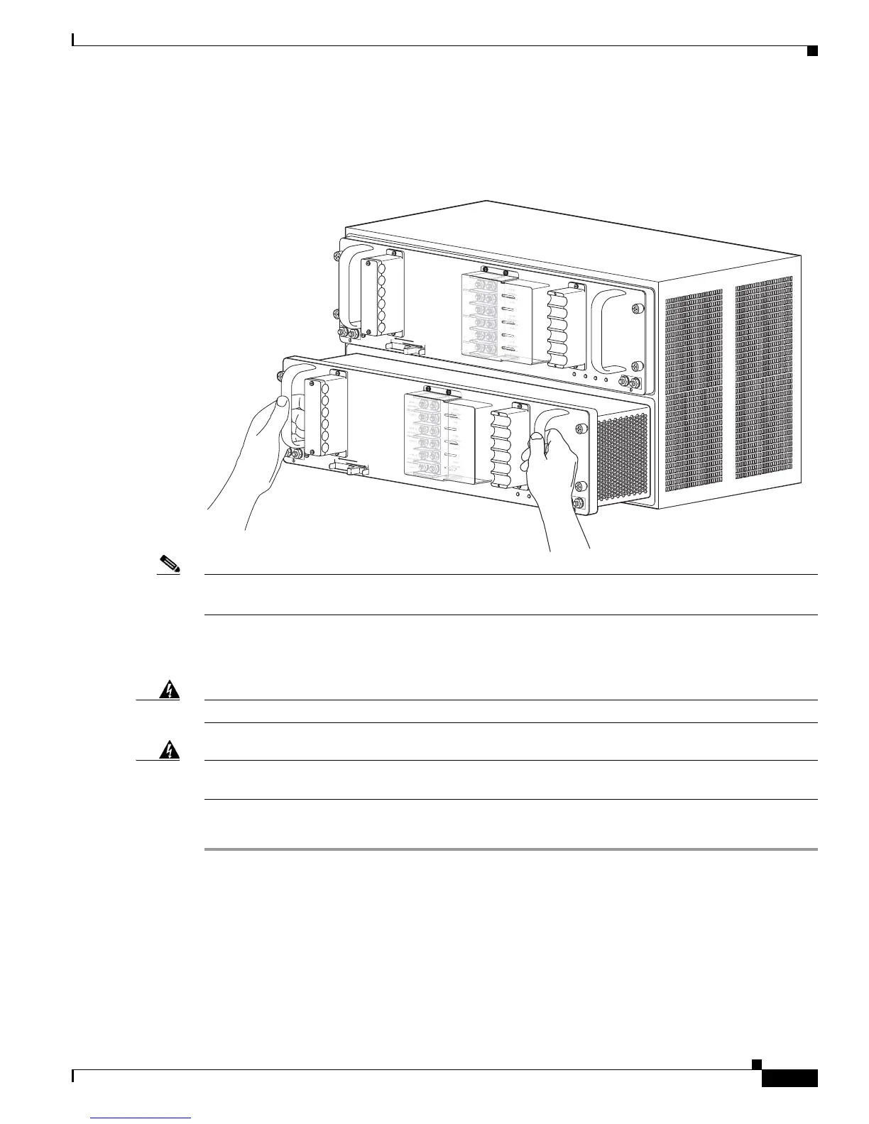
Step 7 Grasp both power supply handles, as shown in Figure 5-25, and slide the power supply completely out
of the chassis.
Figure 5-25 Handling a DC-Input Power Supply
Note If the power supply bay is to remain empty, install a blank power supply filler plate (Cisco part number
800-28533-01) over the opening, and secure it with the captive installation screws
Removing a WS-CDC-2500W Power Supply from a Cisco 7609 Router
Warning
Before performing any of the following procedures, ensure that power is removed from the DC circuit.
Warning
Voltage is present on the backplane when the system is operating. To reduce risk of an electric shock,
keep hands and fingers out of the power supply bays and backplane areas.
Follow these steps to remove a DC-input power supply:
Step 1 Verify that power is off to the DC circuit connected to the DC-input power supply you are removing.
Step 2 Turn the power switch to the Off (0) position on the power supply you are removing (Figure 5-26).
Turning the power switch off also disengages a pawl that unlocks the power supply from the chassis.
252584
PWR-4500-DC
INPUT1
OK
INPUT2
OK
FAN
OK
OUTPUT
FAI L
SWITCH MUST BE IN OFF “O” POSITION
TO INSTALL/REMOVE POWER SUPPLY.
FASTENERS MUST BE FULLY ENGAGED
PRIOR TO OPERATING POWER SUPPLY.
40A
-VE-3
INSTALL
REMOVE
PWR-4500-DC
INPUT1
OK
INPUT2
OK
FAN
OK
OUTPUT
FAI L
SWITCH MUST BE IN OFF “O” POSITION
TO INSTALL/REMOVE POWER SUPPLY.
FASTENERS MUST BE FULLY ENGAGED
PRIOR TO OPERATING POWER SUPPLY.
INSTALL
REMOVE
+VE-1
48V-60V
40A
-VE-1
+VE-2
48V-60V
40A
-VE-2
+VE-3
48V-60V
40A
-VE-3