5-24
Cisco 7600 Series Router Installation Guide
OL-4503-26
Chapter 5 Removal and Replacement Procedures
Removing and Replacing the Power Supply
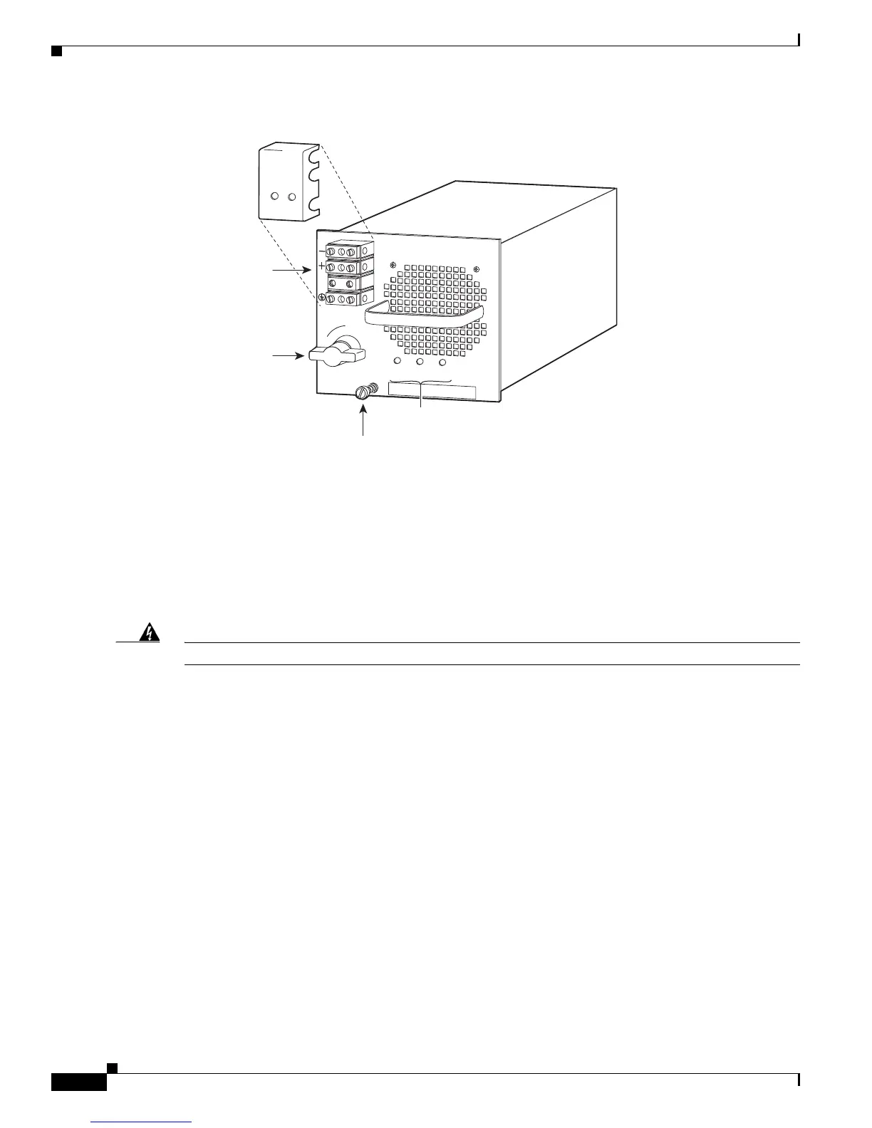
Figure 5-26 DC-Input Front Panel for 2500-W DC-Input Power Supply
Step 3 Remove the two screws securing the terminal block cover, and slide the cover off the terminal block
(
Figure 5-26).
Step 4 Disconnect the DC-input wires from the terminal block (Figure 5-27) in this order:
• Positive (+)
• Negative (-)
• Ground
Warning
When installing the unit, the ground connection must always be made first and disconnected last.
INPUT
OK
FAN
OK
OUTPUT
FAIL
I
0
85906
Power
switch
DC power cable
terminal block
Terminal block
cover
Status LEDs
Captive installation
screw