5-36
Cisco 7600 Series Router Installation Guide
OL-4503-26
Chapter 5 Removal and Replacement Procedures
Removing and Replacing the Power Supply
Step 2 Turn the power switch to the Off (0) position on the power supply you are removing (Figure 5-40).
Turning the power switch off also disengages a pawl that unlocks the power supply from the chassis.
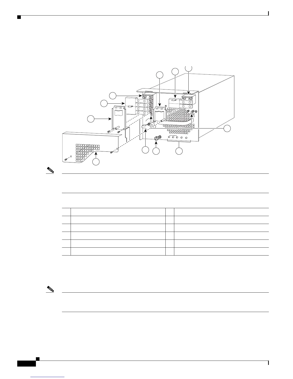
Figure 5-40 DC-Input Front Panel for 4000-W DC-Input Power Supply
Note Figure 5-40 shows PWR-4000-DC with an outer terminal block cover; an earlier version of this power
supply does not have an outer terminal block cover. To order a retrofit kit use part number
CVR-4000DC-TERM=.
Step 3 Remove the two A4 screws securing the outer terminal block cover, and remove the cover from the power
supply (
Figure 5-40).
Step 4 Cut any cable tie-wraps being careful not to cut the DC-input wires.
Note The 4000 W DC-input power supply provides voltages of 2700 W or 4000 W for single and redundant
configurations. Some configurations require cable tie-wraps. For more information, refer to
Installing a
PWR-4000-DC Power Supply in a Cisco 7613 Router, page 5-91.
Step 5 Remove the two screws securing the left inner terminal block cover and one screw securing the right
inner terminal block cover. Remove both inner terminal block covers.
1 Inner terminal block cover 7 Power switch
2 Plastic insulator 8 Outer terminal block cover
3 DC power cable terminal block 2 (TB2) 9 Inner terminal block cover
4 Ground 10 Plastic insulator
5 Status LEDs 11 DC power cable terminal block 1 (TB1)
6 Captive installation screw
IN
P
U
T O
K
FA
N
O
K
O
U
TP
U
T
FA
IL
I
0
101397
1
3
2
5
11
6
3
1
10
+
V
E-1
-
VE
-1
+
VE
-2
-
VE-2
+
VE-3
-
VE-3
8
7
9
4
2