5-37
Cisco 7600 Series Router Installation Guide
OL-4503-26
Chapter 5 Removal and Replacement Procedures
Removing and Replacing the Power Supply
Note You must remove three terminal block covers for the 4000 W DC-input power supply.The
left-side inner terminal block cover has two securing screws and the right-side inner terminal
block cover has one securing screw.
Step 6 Remove the plastic insulator from over the terminal area (Figure 5-41).
Step 7 Disconnect the DC-input wires from the terminal block in this order:
• Positive (+)
• Negative (-)
Note You must remove DC-input wires from two terminal blocks for the 4000 W DC-input power
supply (if both terminal blocks are used).
Step 8 Disconnect the PWR-4000-DC power supply ground.
Warning
When installing the unit, the ground connection must always be made first and disconnected last.
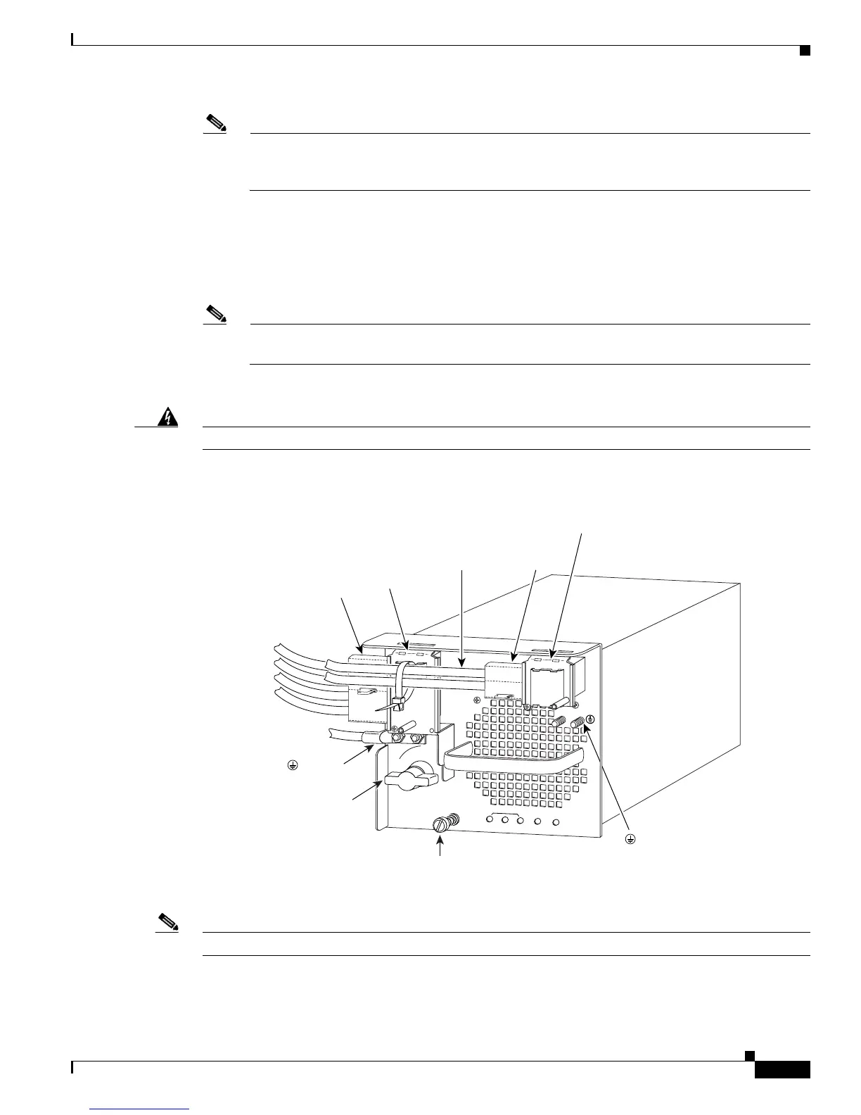
Figure 5-41 DC-Input Wire Connections for 4000-W DC-Input Power Supply
Note Figure 5-41 shows a 4000 W configuration that requires cable tie-wraps.
Step 9 Loosen the captive installation screw on the power supply (Figure 5-41).
114008
3
INPUT OK
FAN
OK
OUTPUT
FAIL
I
0
1
2
Captive
installation
screw
( ) Ground
(+) Positive
( - ) Negative
Power
switch
( ) Ground
(+) Positive
( - ) Negative
Power leads
attached to
terminal block
Terminal
block cover
Plastic
insulator
Power leads
attached to
terminal block
(+) Positive
( - ) Negative
Terminal
block cover
Plastic
insulator