5-107
Cisco 7600 Series Router Installation Guide
OL-4503-26
Chapter 5 Removal and Replacement Procedures
Removing and Replacing the Power Supply
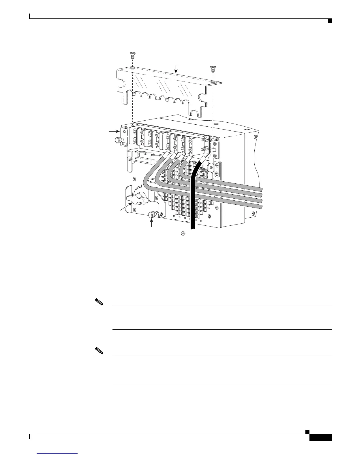
Figure 5-101 DC-Input Wire Connections for 2700-W DC-Input Power Supply, Right Side of Power
Bay
b. From the right side of the power supply, connect the DC-input wires to the terminal block
(
Figure 5-97 and Figure 5-101) in this order:
Negative (-)
Positive (+)
Note When you tighten the terminal nuts, make sure they are snug. Do not over tighten them.
Recommended torque strength is 20 inch-pounds. Over tightening the terminal nuts can
break the terminal block (Maximum torque: 36 inch-pounds).
c. Secure outer block cover.
Note For proper 2800W DC-input redundant power configuration, both pairs of input wires for
one 6000W DC-input power supply must come from the same battery system (A feed); both
pairs of input wires for the other 6000W DC-input power supply must come from another
battery system (B feed).
191290
R
U
N
I
N
S
T
A
L
L
CISCO SYSTEMS, INC
1
2
3
4
INPUT OK
FAN
OK
OUTPUT
FAI L
Captive
installation
screw
Terminal
block cover
( - ) Negative
(+) Positive
( - ) Negative
(+) Positive
Power leads
attached to
terminal block
( ) Ground
Input power
module
Power
switch