Chapter 3 Installing the Switch in a Rack
Rack-Mounting the Switch
3-14
Catalyst 4500 Series Switches Installation Guide
78-14409-08
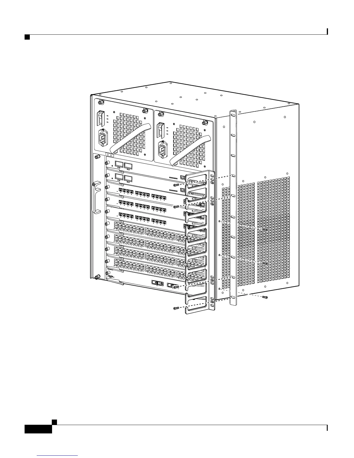
Figure 3-8 Attaching the Cable Guide to the Catalyst 4510R Switch
Step 3 Install the chassis in the rack as follows:
a. Insert the rear of the chassis between the mounting posts.
See Figure 3-9 to see how to install the Catalyst 4503 switch in a rack.
See Figure 3-10 to see how to install the Catalyst 4506 switch in a rack.
See Figure 3-11 to see how to install the Catalyst 4507R switch in a rack.
See Figure 3-12 to see how to install the Catalyst 4510R switch in a rack.
b. Align the mounting holes in the L bracket with the mounting holes in the
equipment rack.
43
42
3
1
2
WS-X4448-GB-RJ45
STATUS
12
11
10
9
8
7
6
5
4
3
2
1
14
13
16
15
28
27
26
25
24
23
22
21
20
19
18
17
30
29
32
31
44
43
42
41
40
39
38
37
36
35
34
33
46
45
48
47
1
0/1
00
BA
S
E
-T
X
E
T
H
E
R
N
ET
M
U
LT
I-
SP
E
ED
G
IG
A
B
IT
E
TH
E
R
N
ET
S
W
IT
C
H
IN
G
M
O
D
UL
E
WS-X4448-GB-RJ45
STATUS
12
11
10
9
8
7
6
5
4
3
2
1
14
13
16
15
28
27
26
25
24
23
22
21
20
19
18
17
30
29
32
31
44
43
42
41
40
39
38
37
36
35
34
33
46
45
48
47
1
0/10
0B
A
SE
-T
X
E
TH
E
RN
E
T
M
U
LTI
-S
P
E
ED
G
IG
A
B
IT
ET
H
ER
N
ET
S
W
IT
C
HI
NG
M
O
D
U
LE
WS-X4448-GB-RJ45
STATUS
12
11
10
9
8
7
6
5
4
3
2
1
14
13
16
15
28
27
26
25
24
23
22
21
20
19
18
17
30
29
32
31
44
43
42
41
40
39
38
37
36
35
34
33
46
45
48
47
10
/1
00B
AS
E
-T
X
ET
H
ER
N
ET
M
U
LT
I-S
P
E
ED
G
IG
A
BI
T E
T
HE
R
N
ET
S
W
IT
CH
IN
G
M
O
D
UL
E
WS-X4448-GB-RJ45
STATUS
12
11
10
9
8
7
6
5
4
3
2
1
14
13
16
15
28
27
26
25
24
23
22
21
20
19
18
17
30
29
32
31
44
43
42
41
40
39
38
37
36
35
34
33
46
45
48
47
1
0/10
0B
A
S
E
-T
X
ET
H
E
R
NE
T
MU
L
TI
-S
PE
E
D
G
IG
A
B
IT
E
T
H
ER
N
E
T
S
W
IT
C
HIN
G
M
O
D
UL
E
1
STATUS
W
S-X4412-2GB-TX
2
3
4
5
6
7
8
9
10
11
12
17
1
STATUS
WS-X4412-2GB-TX
2
3
4
5
6
7
8
9
10
11
12
17
1
STATUS
WS-X4412-2G
B-TX
2
3
4
5
6
7
8
9
10
11
12
17
UPLINK
UPLINK
CONSOLE
10/100
BASE-TX
STATUS
UPLINK
UPLINK
CONSOLE
10/100
BASE-TX
STATUS
94939

 Loading...


