4-13
Catalyst 4500 Series Switches Installation Guide
78-14409-08
Chapter 4 Removing and Replacing FRUs
Removing and Replacing the Power Supply
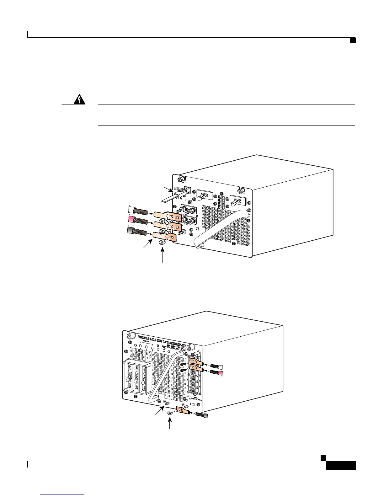
Step 5 Disconnect the DC-input wires from the terminal block. Disconnect the ground
wire last (see
Figure 4-13 or Figure 4-14).
Warning
When installing or replacing the unit, the ground connection must always be
made first and disconnected last.
Statement 1046
Figure 4-13 Connecting the DC-Input Wires
Figure 4-14 Connecting the DC-Input Wires (Triple-input Power Supply)
RS-485 serial
communnication
connector
79161
Grounding lug
Grounding lug nuts
DC-input wires
Negative
Positive
Ground
154727
1
-
+
-
+
-
+
2
3
Grounding lugs (2)
Grounding lug nut
DC-input wires
Negative
Positive
Ground

 Loading...


