EasyManuals Logo

Cisco Catalyst 4500 Series Installation Guide

Cisco Catalyst 4500 Series
194 pages
To Next Page IconTo Next Page
To Previous Page IconTo Previous Page
Page #142 background imageLoading...
Page #142 background image
Chapter 4 Removing and Replacing FRUs
Replacing Backplane Modules on a Catalyst 4507R or 4510R Switch
4-28
Catalyst 4500 Series Switches Installation Guide
78-14409-08
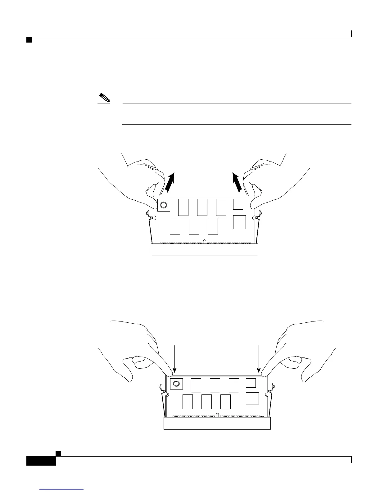
Step 7 Pull out the module while holding the top left and top right corners. (See
Figure 4-24.)
Note When handling the modules, do not touch the chips or the gold edge
contacts on the module.
Figure 4-24 Removing the Module
Step 8 Put the replacement module in at roughly a 30 degree angle, and gently push the
module down. Make sure you apply force evenly on the left and right. (See
Figure 4-25.)
Figure 4-25 Seating the Replacement Module
130660
130661

Table of Contents

Other manuals for Cisco Catalyst 4500 Series

Questions and Answers:

Question and Answer IconNeed help?

Do you have a question about the Cisco Catalyst 4500 Series and is the answer not in the manual?

Cisco Catalyst 4500 Series Specifications

General IconGeneral
SeriesCatalyst 4500 Series
CategorySwitch
Layer SupportLayer 2, Layer 3
Form FactorModular chassis
StackableNo
Chassis Slots3, 6, 7, 10
Power Supply OptionsAC, DC
RedundancyPower supply, Supervisor engine
Network ManagementCisco IOS Software CLI, SNMP, Cisco Prime Infrastructure
FeaturesSecurity, QoS
Port DensityUp to 384 ports per chassis
Security Features802.1X, ACLs, DHCP Snooping, Dynamic ARP Inspection, IP Source Guard
Supervisor Engine8-E

Related product manuals