Step 2 The outer face of the rack mount bracket ear, the part that typically mounts to an equipment rack,
should be placed against the side of the router. Use the spacers provided to adapt the larger obround holes
down to smaller holes for the screws to fit into.
Step 3 The brackets should be located diagonally from each other as shown in the figure below.
Step 4 Tighten the screws to a torque value of 15 to 18 inch-lb. (1.7 to 2.0 N-m).
Step 5 Use #6 or 4mm hardware to attach the brackets to the wall. At least 4 screws should be used per
bracket, 8 screws in total. The screw length should be a minimum of 1 inch in length (25.4 mm).
The customer supplies the appropriate hardware. Each mounting bracket has 8 holes that can be used
for the mounting fasteners.
Note
Step 6 Route the cables so that they do not put a strain on the connectors or mounting hardware.
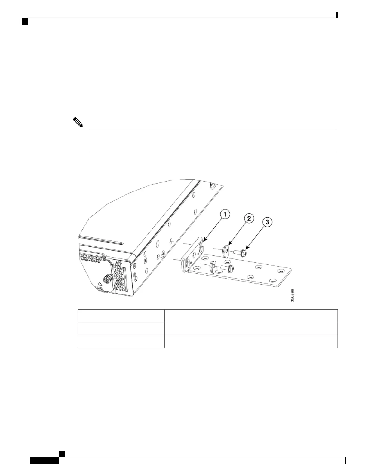
Figure 28: Attach Wall Mount Brackets (C8300-1N1S-4T2X|6T)
19-inches bracket1
Plastic spacer2
#6-32 PHMS3
Hardware Installation Guide for Cisco Catalyst 8300 Series Edge Platforms
44
Install and Connect
Attach Cisco Cisco Catalyst 8300 Series Edge Platforms on a Wall