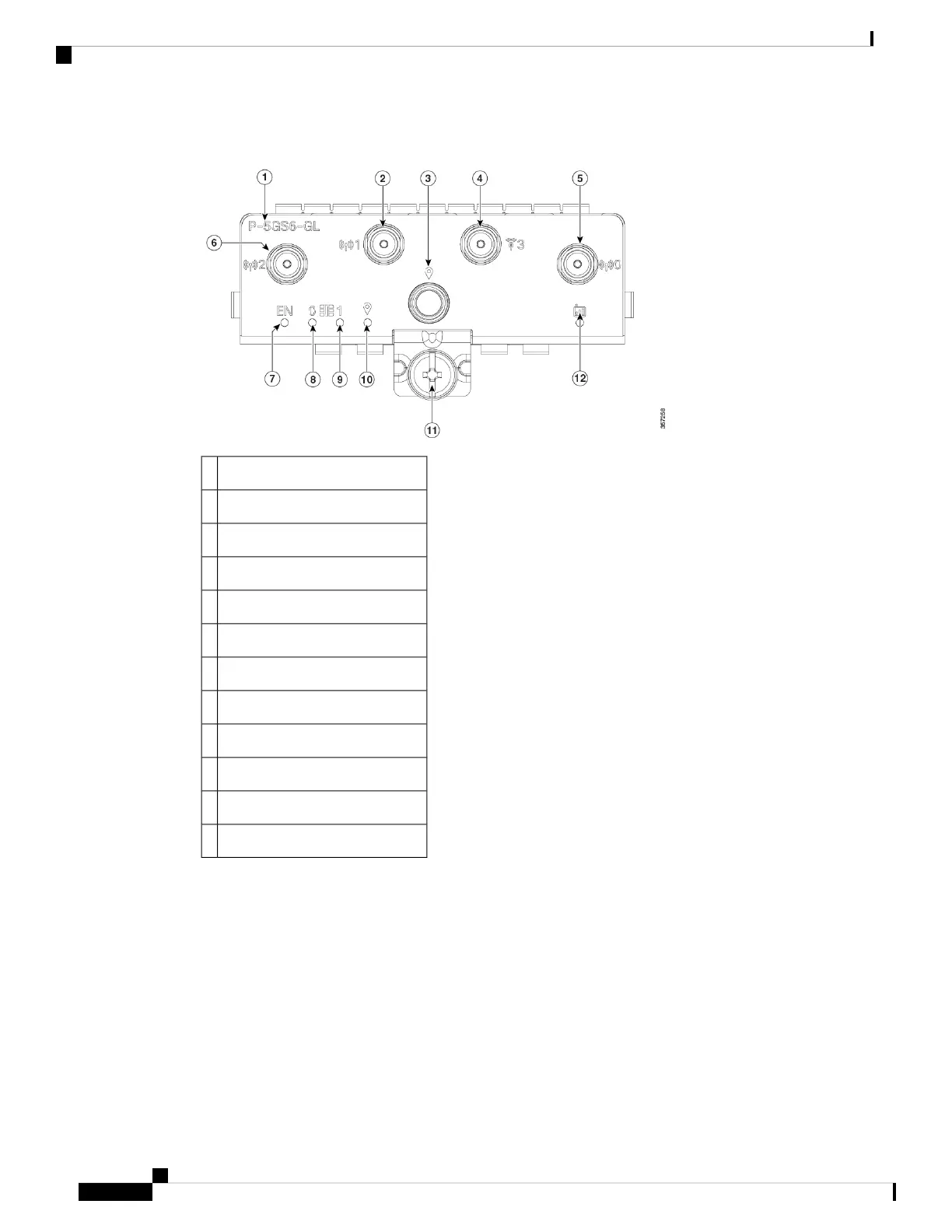
Figure 80: 5G Pluggable Interface Module - P-5GS6-GL
PID1
Antenna 1 (SMA)2
GPS (SMA)3
Antenna 3 (SMA, reception only)4
Antenna 0 (SMA)5
Antenna 2 (SMA)6
Enable LED7
SIM 0 LED8
SIM 1 LED9
GPS LED10
M3.5 thumb-screw11
Service LED12
Configuring a Pluggable Interface Module
To insert the antenna in the Pluggable Interface Module, perform the below steps:
Hardware Installation Guide for Cisco Catalyst 8300 Series Edge Platforms
110
Cisco Catalyst Pluggable Interface Module
Configuring a Pluggable Interface Module

 Loading...