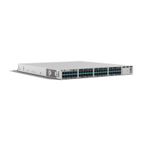
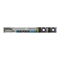
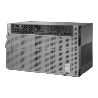
This equipment is suitable for installation in Network Telecommunications Facilities and locations
where the NEC applies. The equipment is suitable for installation as part of the Common Bonding
Network (CBN).
Note
• For NEC-compliant grounding, use size 14 AWG (2 mm² ) or larger copper wire and an appropriate
user-supplied ring terminal with an inner diameter of 1/4 in. (5–7 mm)
• AWG 10 (4 mm²) or larger wire for EN/IEC 60950-1 and EN/IEC 62368-1 compliant chassis grounding
The grounding wire should be sized according to local and national installation requirements. The above
recommended AWG values for NEBS-compliant, NEC-compliant, EN/IEC 60950-1 and EN/IEC 62368-1
as the minimum requirement respectively, the higher AWG value recommendation also with the higher
priority, this means AWG 10 is the minimum requirement only when NEBS is not required. Commercially
available 6-AWG grounding wire is always preferred from the chassis to the rack ground or directly to
the common bonding network (CBN). The length of the grounding wire depends on the proximity of
the switch to proper grounding facilities.
Note
To install the ground connection for your device, perform the following steps:
Step 1 Strip one end of the ground wire to the length required for the ground lug or terminal.
• For the ground lug—approximately 0.75 inch (20 mm)
• For user-provided ring terminal—as required
Step 2 Crimp the ground wire to the ground lug or ring terminal, using a crimp tool of the appropriate size.
Step 3 Attach the ground lug or ring terminal to the chassis as shown in Chassis Grounding section. For a ground lug, use the
two screws with captive locking washers provided. For a ring terminal, use one of the screws provided. Tighten the screws
to a torque of 8 to 10 in-lb (0.9 to 1.1 N-m).
Hardware Installation Guide for Cisco Catalyst 8300 Series Edge Platforms
46
Install and Connect
Chassis Grounding

 Loading...


