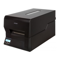
Chapter 2 Operating Principles
CL-E720DT 2-2
CHAPTER 2 OPERATING PRINCIPLES
TABLE OF CONTENTS
2-1. Operation of Each Mechanism ....................................................................................... 2-4
2-1-1. Locations and Functions of Major Electrical Parts ............................................. 2-4
2-1-2. Media Feed/Printing Mechanism........................................................................ 2-5
2-1-3. Label/Tag Detection Mechanism ........................................................................2-6
2-1-4. Print Head Up/Down Detection Mechanism....................................................... 2-9
2-1-5. Head Balance Adjustment Mechanism .............................................................. 2-10
2-1-6. Media Thickness Adjustment Mechanism .......................................................... 2-11
2-2.
Operation of Control Parts .............................................................................................. 2-12
2-2-1. Configuration of Printer ...................................................................................... 2-12
(1) Filter & power supply section..................................................................... 2-12
(2) SA Main PCB............................................................................................. 2-12
(3) Operation panel (SA Opepane PCB) ......................................................... 2-12
(4) Thermal print head .................................................................................... 2-13
(5) Sensors ..................................................................................................... 2-13
(6) Motor ......................................................................................................... 2-13
(7) USB I/F (USB2.0 compatible full-speed mode/high-speed mode).............2-13
(8) Wired LAN I/F ............................................................................................2-13
(9) Serial I/F (RS-232C) (Option) .................................................................... 2-13
(10) Parallel I/F (IEEE1284) (Option)................................................................ 2-13
(11) Wireless LAN I/F (Option).......................................................................... 2-13
2-2-2.
Operation of Control Unit ................................................................................... 2-14
(1) CPU ........................................................................................................... 2-15
(2) Flash ROM ................................................................................................ 2-15
(3) SDRAM (Synchronous dynamic RAM)...................................................... 2-15
(4) FPGA......................................................................................................... 2-15
(5) Head control .............................................................................................. 2-15
(6) Stepping motor driver (For “SA PF Motor”)................................................ 2-15
(7) Buzzer ....................................................................................................... 2-15
2-2-3. Memory map ...................................................................................................... 2-16
2-2-4. Sensors ..............................................................................................................2-17
(1) Head up sensor (SA Head Up Sensor PCB) ............................................. 2-17
(2) Transparent sensor (SA TRA Sen PCB) and reflective sensor
(SA Ref Sensor PCB) ................................................................................ 2-18
(3) Head temperature sensor.......................................................................... 2-20
(4) PF motor temperature sensor.................................................................... 2-21
2-2-5.
Drivers................................................................................................................ 2-23
(1) PF motor driver.......................................................................................... 2-23
(2) Head driver ................................................................................................2-24
(3) Buzzer driver ............................................................................................. 2-25
2-2-6.
Other circuits ...................................................................................................... 2-26
(1) Power supply circuit................................................................................... 2-26
(2) Reset circuit............................................................................................... 2-27

 Loading...