Chapter 2 Operating Principles
2-1. Operation of Each Mechanism
CL-E720DT 2-4
2-1. Operation of Each Mechanism
This printer is comprised of the following mechanisms:
media feed/printing, label/tag detection, print head up/down detection, head balance adjustment
and media thickness adjustment.
This section describes the operation of each of these mechanisms.
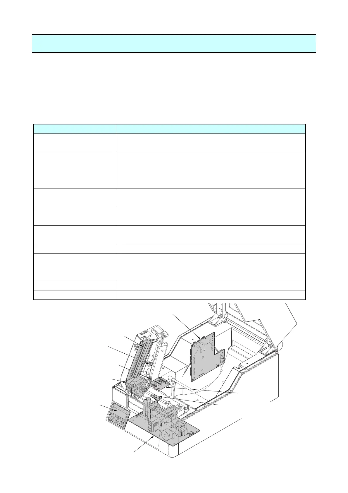
2-1-1. Locations and Functions of Major Electrical Parts
The following shows the locations and functions of major electrical parts.
Part name Description
SA PF Motor This motor feeds media. A thermistor is attached to the motor to
detect the motor temperature.
SA Head It consists of a head driver and thermal elements. The thermal
elements are heated to make printing on media. The thermal
head incorporates a thermistor to detect the thermal head
temperature.
SA Head Up Sensor PCB
(Head Up Sensor)
This sensor is a photointerrupter to detect the print head
position; up or down.
SA TRA Sen PCB
(Transparent Sensor)
This sensor is a photo sensor to detect a label stuck on liner or
U-shaped notches on tag. It also detects the media end.
SA Ref Sensor PCB
(Reflective Sensor)
This sensor is a photo sensor to detect a black mark on tag. It
also detects the media end
SA Main PCB It controls entire printer system.
SA Relay PCB It is a relay PCB located between the “SA Main PCB” and the
“Unit Mechanism”. The optional auto cutter unit or the peeler unit
is connected to this PCB.
SA Opepane PCB It consists of LCD, LED and switches for operation.
Unit Power Supply It converts AC input to DC24 V.
SA Head
SA TRA Sen PCB
(Transparent Sensor)
SA Opepane PCB
SA PF Motor
Unit Power Supply
SA Main PCB
SA Head Up Sensor PCB
(Head Up Sensor)
Relay PCB
SA Ref Sensor PCB
(Reflective Sensor)