Chapter 3 Disassembly and Maintenance
3-6. Disassembly, Reassembly and Lubrication
CL-E720DT 3-26
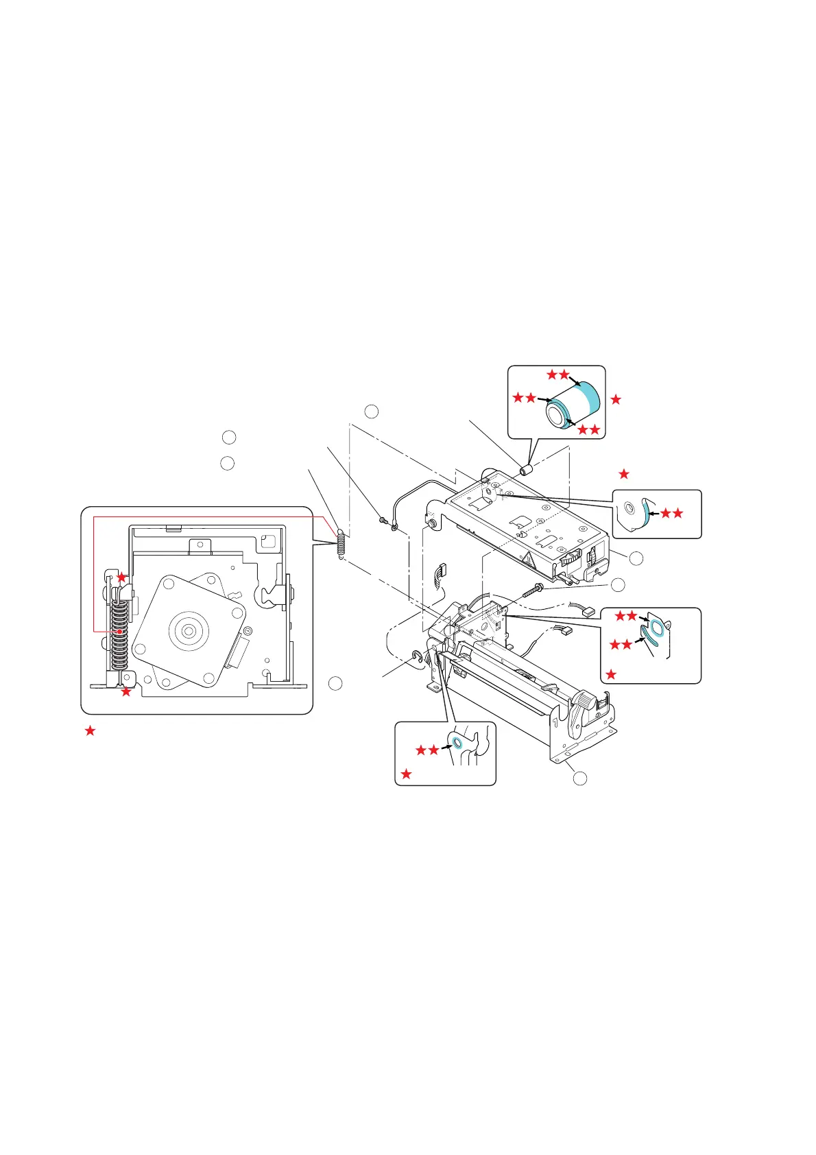
3-6-11. “Unit Head” and “Unit PF”
1. Remove the “Cover PF Motor”. Refer to “3-6-2 Cover PF Motor”.
2. Remove the “Unit Opepane”. Refer to “3-6-3(1) Unit Opepane”.
3.
Remove the “Case” and “Cover Steel L”. Refer to “3-6-4 Case”.
4.
Remove all connectors from the “SA Main PCB”. Refer to “3-6-5(1) “SA Main PCB”
Connectors”.
5. Remove the “Unit Mechanism”. Refer to “3-6-6 Unit Mechanism”.
6.
Remove the 1 screw (BH M3.0x4 (NI)) () and detach the earth wire of the “Unit Head” ().
7. Open the “Unit Head” () and disengage the “Spring Head Up” ().
NOTE: At this time, hold the “Unit Head” () as it can fall off.
8. Disengage the 1 E-ring (E-Ring 4.0) (), and then remove the 1 screw (NO2 PH (SW+PW)
M4.0x16 (NI)) () and “Shaft Head Holder” ().
9. Remove the “Unit Head” () from the “Unit PF” ().
Notes on reassembling:
• When assembling parts, apply FLOIL G-311S to the following places shown by the mark “
”.
A: Hole (front left). Circumference surface of the hole (on both sides) and inside the hole
B: Hole and projection (rear left). Circumference surface of the hole (on both sides) and along
the projection surface.
C: Along the contacting surface (rear left).
D: 3 surfaces on the “Shaft Head Holder” ().
Hooks for “Spring Head Up” () (2 places)
• When mounting the “Shaft Head Holder” (), be sure that its mounting direction is correct.
D
FLOILG-311S
C
B
A
FLOILG-311S
FLOILG-311S
FLOILG-311S
FLOILG-311S
Shaft Head Holder
[Left side view]
BH M3.0x4 (NI)
Spring Head Up
E-Ring 4.0
NO2 PH (SW+PW)
M4.0x16 (NI)
Unit PF
Unit Head
2
4
5
3
1
6
7