ARES 506-606 - 02.2005 - GB
G.12
USING THE LINKAGE
If indicator light (6) is on, proceed as follows:
- Cancel force control by turning adjustment knob (8) to the left.
- Bring the memory button (1) to stop position (III), then to work
position (II).
- Identify the actual position of the arms, using the
position/depth adjustment control (2) until the safety indicator
light goes off.
The light goes out and the linkage is operational.
MALFUNCTIONS
Flashing: The rate of flashing identifies the type of fault. Some
linkage functions remain operational. Refer to your approved
CLAAS repair agent.
POSITION CONTROL
- Set selector (1) on the working position .
- Turn button (2) to the right (clockwise) to raise the linkage.
- Turn button (2) to the left (counter-clockwise) to lower the
linkage.
- Each position of the button corresponds to a position of the
lifting arms.
- The mechanical stop (A) is used as an indication when the
position of knob (2) has been changed during work.
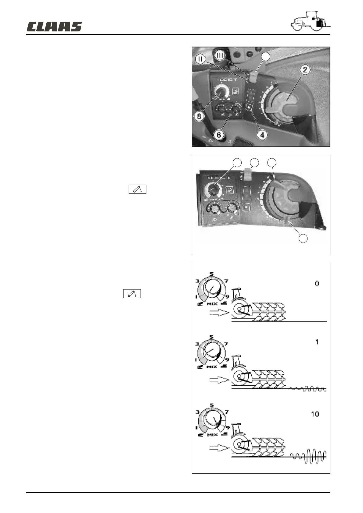
FORCE CONTROL
To activate the force control, proceed as follows:
- Place selector (1) in working position .
- Adjust the tool working depth with button (2) (see position
control).
- Adjust the force control sensitivity using button (8): This button
alters the range of the linkage.
To increase the force control sensitivity, turn button (8) clockwise
and to decrease, turn the button (8) counter-clockwise.
- This adjustment works over a scale from 0 to 10.
Example of sensitivity settings:
0 = linkage used in position display mode, no variation possible ;
1 = linkage used in force control mode, with small variations ;
10 = linkage used in force control mode, with large variations.
382hsn20
382hsn21
382hsn23
1
18 2
A