ARES 506-606 - 02.2005 - GB
G.13
UPPER LIMIT
This limits the top part of the linkage travel to prevent large
implements touching the cab or while shaft-driven implements
are being used.
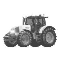
- Place top stop button (7) in minimum position towards marker
–.
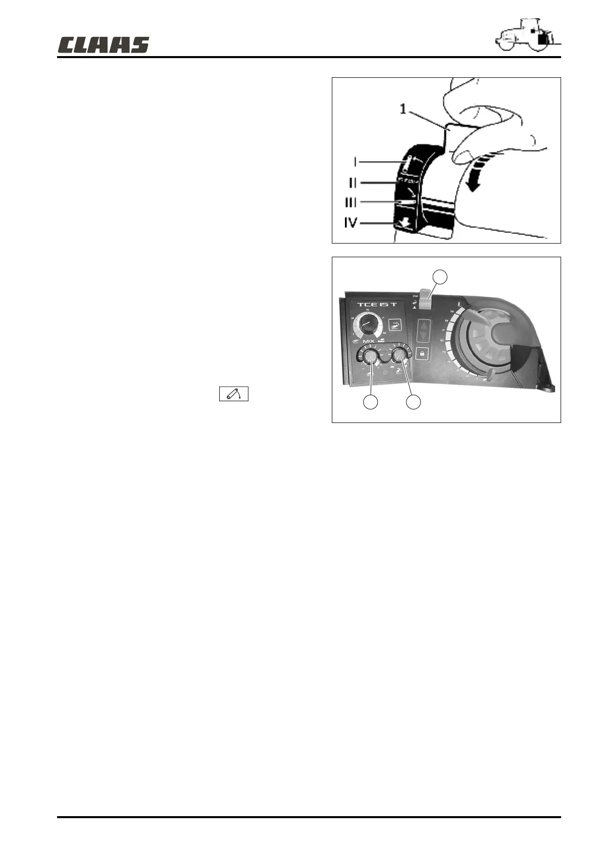
- Set the mode selector (1) to high position (I).
- Then adjust the top position as required, using button (7).
- Turning the button to the right (clockwise) will increase the
height of the linkage arms at top limit.
- Turning the button to the left (counterclockwise) will decrease
the height of the linkage arms at top limit.
- Adjustment is to be carried out at the top section of linkage
travel.
Note: The top limit position will never be exceeded by
another linkage command (position, force or external
controls).
LOWERING SPEED
1 - Set the selector (1) to high position (II).
2 - Using button (5), select the minimum lowering speed.
3 - Set the selector (1) to low position .
Repeat operations 1 to 3 and modify the lowering speed using
button (5):
- Turning to the right (clockwise) increases linkage arm descent
rate.
- Turning the button to the left (counterclockwise) will decrease
the height of the linkage arms.
Important: Before lowering any heavy implement to a hard
surface, set button (5) on the tortoise position.
382hsn24
382hsn25
7
1
5