CHAPTER!
GENERAL DESCRIPTION AND PRINCIPLES OF OPERATION
OIL
STRAINEfl
OIL
SUPPLY
PFESSUAE
GAUGe
WATER
FIEUEF
VALVES
HOTWA~
OILHEATER
.
BVP..a&VAL\IE
EI009"1"EF!
WATER
PUMP
0Pe=IA11NG
TEMPeRATURE.
HIGHUMIT
•
T'EJIIFIEAA
TURE
AND
MOOULA11NG
'T"EMP'ERA
TUAE
CONTROLS
HOT
WATER
OIL
HEATER
COIL
WATER
'T"EMPERA
TUAE
GAUGE
NOTE:
FOR
STREAM
COMPONENTS
~TO
FIGURE 1-8
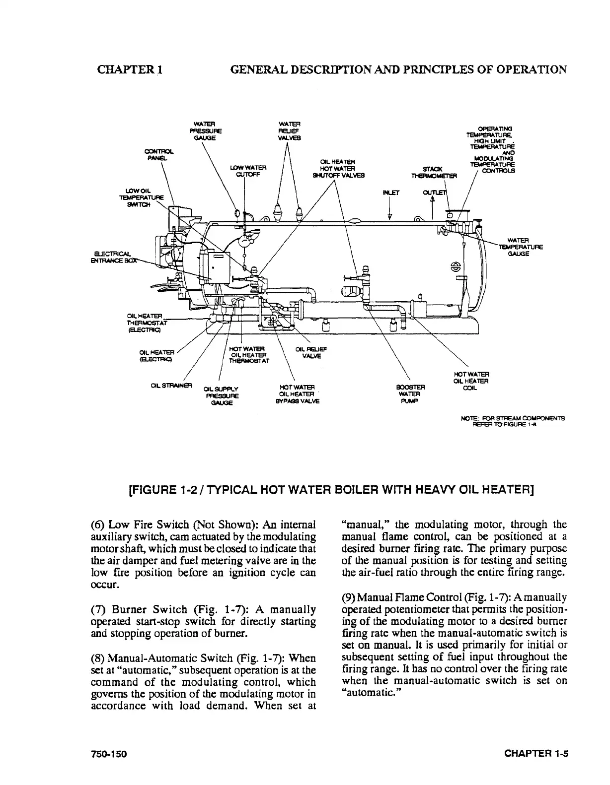
[FIGURE 1-2 I TYPICAL HOT WATER BOILER WITH HEAVY
OIL
HEATER]
(6) Low Fire Switch (Not Shown): An internal
auxiliary switch, cam actuated by the modulating
motor shaft, which must be closed
to
indicate that
the air damper and fuel metering valve are
in
the
low fire position before an ignition cycle can
occur.
(7)
Burner
Switch
(Fig.
1·7):
A
manually
operated start·stop switch for directly starting
and stopping operation
of
burner.
(8)
Manual*Automatic Switch (Fig. 1-7): When
set at "automatic," subsequent operation
is
at the
command
of
the
modulating
control, which
governs the position
of
the modulating motor
in
accordance with load demand.
When
set at
750-150
"manual," the modulating motor, through the
manual flame control, can
be positioned at a
desired burner
firing rate.
The
primary purpose
of
the manual position
is
for testing and setting
the air-fuel ratio through the entire firing range.
(9) Manual Flame Control (Fig. 1-7): A manually
operated potentiometer that permits the
position-
ing
of
the modulating motor to a desired burner
firing rate when the manual·automatic switch
is
set on manual.
It
is
used primarily for initial or
subsequent setting
of
fuel input throughout the
frring range. It has no control over the firing rate
when the manual-automatic switch
is
set on
"automatic."
CHAPTER
1..5