CHAPTERS
Final adjustment to fuel input must be made to
produce a minimum
of
smoke. A maximum
smoke spot density
of
a No. 2 for light oil, or a
No. 4 for heavy oil
is acceptable, as measured in
conformance to ASTMD 2156-63T.
Through the use
of
the manual flame control,
slowly bring the unit to high fire by stages while
monitoring combustion for overly rich or lean
conditions.
At
the high fire position, the air
damper should be fully opened and the air and oil
pressure readings should
be
on the order
of
those
given in Chapter 4.
Take a flue gas analysis reading at this point.
If
necessary, make adjustments to the fuel oil
con~
troller to increase
or
decrease oil pressure. This
should be done before making any effort to adjust
the screws in the metering cam. Ideally, the cam
profile spring should
be
as
close to the cam
casting
as
practical and it
is
more desirable
to
lower the oil pressure
to
reduce flow,
if
neces-
sary, than to extend adjusting screws to an ex-
treme position
in
an effort to cut back on flow.
After making certain that the air control damper
and its linkage are operating properly to provide
. the proper amount
of
secondary air and that fuel
oil pressure settings are correct, final adjustment
can be made,
if
necessary,
to
the oil modulating
cam to obtain a constant
fuel~air
ratio through the
entire firing range.
Since the input
of
combustion air is ordinarily
fixed at any given point
in
the modulating cycle,
the flue gas reading
is determined by varying the
input
of
fuel at that setting. This adjustment
is
made to the metering cam by means
of
adjusting
screws, which are turned out (counterclockwise
from hex-socket end)
to increase the flow
of
fuel
and in (clockwise from hex-socket end) to
decrease
it.
Flow rate
is
highest when the cam
follower assembly is closest
to jackshaft. See
Figure 5-8.
If oil pressure, primary air pressure, and linkages
are properly adjusted, the metering cam should
require minimal adjustment.
If
adjustment
is
necessary, follow this recom-
mended procedure.
CHAPTER 5-20
ADJUSTMENT PROCEDURES
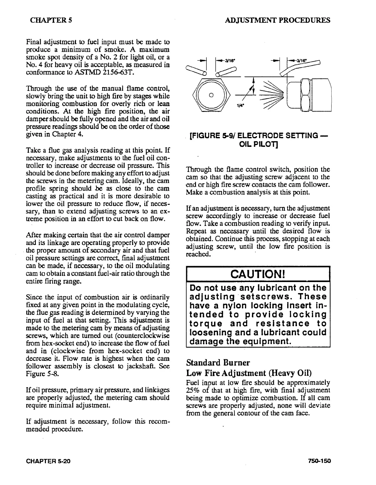
[FIGURE 5-9/ ELECTRODE
SETTING-
OIL
PILOT]
Through the flame control switch, position the
cam so that the adjusting screw adjacent
to
the
end or high fire screw contacts the cam follower.
Make a combustion analysis at this point.
If an adjustment
is
necessary, turn the adjustment
screw accordingly to increase or decrease fuel
flow. Take a combustion reading
to verify input.
Repeat
as
necessary until the desired flow is
obtained. Continue this process, stopping at each
adjusting screw, until the low fire position is
reached.
·
CAUTION!
Do
not
use
any
lubricant
on
the
adjusting·
setscrews.
These
have a
nylon
locking
Insert
in-
tended
to
provide
locking
torque
and
resistance
to
loosening
and a
lubricant
could
damage
the
equipment.
Standard Burner
Low
Fire Adjustment (Heavy Oil)
Fuel input at low fire should be approximately
25%
of
that at high fire, with final adjustment
being made
to optimize combustion. If all cam
screws are properly adjusted, none will deviate
from the general contour
of
the cam face.
750-150