CHAPTERS
JAC<SHAFT-:r-
FIOTARV
AIR
OMtF"et
.AIW
ROTARY
AIR
DAMPER
II
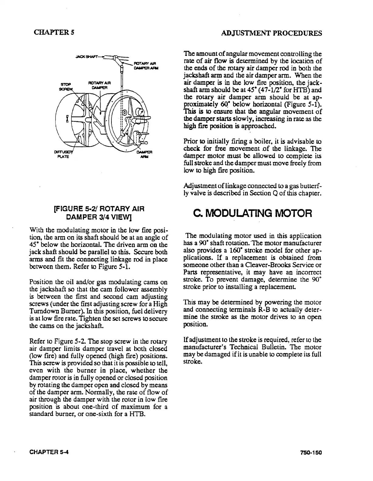
[FIGURE 5·2/ ROTARY
AIR
CAMPER 3/4
VIEVV]
With the modulating motor
in
the low fire posi-
tion, the arm on its shaft should
be
at an angle
of
45° below the horizontal.
The
driven arm on the
jack shaft should
be
parallel to this. Secure both
arms and fit the connecting linkage rod in place
between them. Refer
to
Figure 5-1.
Position the oil and/or gas modulating cams on
the jackshaft so that the cam follower assembly
is
between the first and second cam adjusting
screws (under the first adjusting screw for a High
Turndown Burner).
In
this position, fuel delivery
is
at low fire rate. Tighten the set screws to secure
the cams
on
the jacks haft.
Refer to Figure 5-2.
The
stop screw in the rotary
air damper limits damper travel at both closed
(low fire) and fully opened (high fire) positions.
This
screw is provided
so
that it is possible to tell,
even
with
the
burner
in place,
whether
the
damper rotor is in fully opened
or
closed position
by
rotating the damper open and closed by means
of
the damper arm. Normally, the rate
of
flow
of
air through the damper with the rotor in low fire
position
is
about one-third
of
maximum for a
standard burner,
or
one~sixth
for a HTB.
CHAPTER 5-4
ADJUSTMENT PROCEDURES
The
amount
of
angular movement controlling the
rate
of
air flow is determined by the location
of
the ends
of
the rotary air damper rod in both the
jackshaft arm and the air damper arm. When the
air damper
is
in
the low fire position, the
jack-
shaft arm should
be
at 45• (47-1/2° for HTB) and
the rotary
air
damper
arm should
be
at ap-
proximately
6Q•
below horizontal (Figure 5-1).
This is to ensure that the angular movement
of
the damper starts slowly, increasing in rate as the
high
fire position
is
approached.
Prior
to initially firing a boiler, it
is
advisable to
check for
free
movement .of the linkage. The
damper motor must be allowed to complete its
full stroke
and
the damper must move freely from
low
to high fire position.
Adjustment
of
linkage connected to a gas butterf-
ly
valve
is
described in Section Q
of
this chapter.
C.
MODULATING
MOTOR
The
modulating motor
used
in this application
has a
90o
shaft rotation.·The motor manufacturer
also provides a
160° stroke model for other
ap·
plications.
If
a replacement
is
obtained from
someone other than a Cleaver-Brooks Service
or
Parts representative, it may have an incorrect
stroke.
To
prevent damage, determine the 90°
stroke prior to installing a replacement.
This may
be
determined by powering the motor
and connecting terminals R-B to actually deter-
mine the stroke as the motor drives
to
an open
position.
If
adjustment to the stroke
is
required, refer
to
the
manufacturer's Technical Bulletin. The motor
may be damaged
if
it is unable to complete its full
stroke.
750-150