CHAPTER!
GENERAL
DESCRIPTION
AND
PRINCIPLES
OF
OPERATION
OIL
SUPPLY
PAESSUFE
GAUGe
NOTE:
FOR
HOT
WATER
COMPONENTS
FEFERTO
FIGURE
1·2
STEAM
PRESSUFE
GAUOE
STEAM
PRESSURE
FEGULATOR
STEAM
SHUTOFF
VALVE
~~=C~~l===~~aSTEAM
1..-'-_._-"""'"'"..,..,_
__
-i.-.f
__
INLET
OIL
INLET
FROM
TANK
STEAM
HEA
SOLENOIOV
LOW
PRESSURE
BOflERS
ONLY
NOTE:
AU
CONOENSA
TE
FROM
STEAM
TRAP
MUST
BE
WASTED
AND
PIPED
TO
A
SAFE
POINT
OF
DISCHARGE.
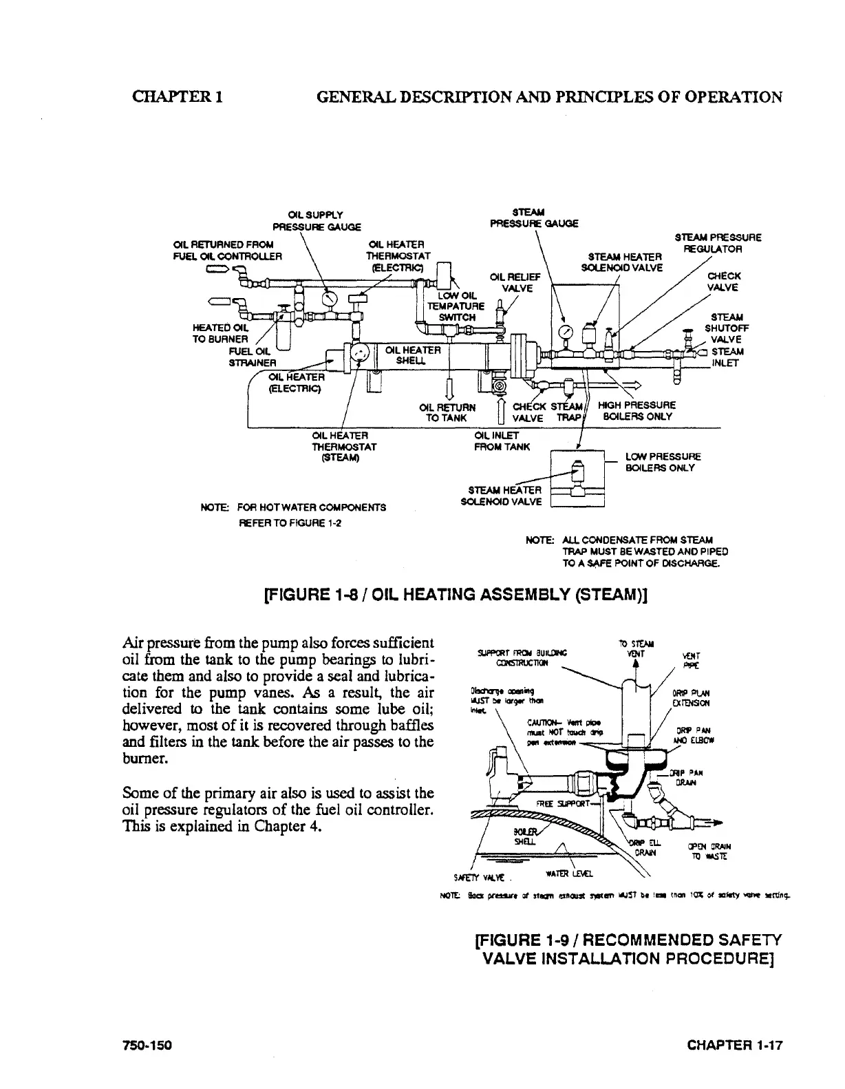
[FIGURE
1-8/
OIL
HEATING
ASSEMBLY
(STEAM)]
Air pressure from the pump also forces sufficient
oil from the tank
to
the pump bearings to lubri-
cate them and also
to
provide a seal and lubrica-
tion for the pump vanes.
As a result, the air
delivered
to the tank contains some lube oil;
however, most
of
it is recovered through baffles
and filters
in the tank before the air passes
to
the
burner.
Some
of
the primary air also is
used
to
assist the
oil pressure regulators
of
the fuel oil controller.
This
is
explained in Chapter 4.
750-150
ro
sro.M
SIJIIfii(.Jtf
F'RCII
aUIU'IHC
~T
a::lNS't'RUCTia.
[FIGURE
1·9/
RECOMMENDED SAFETY
VALVE
INSTALLATION PROCEDURE]
CHAPTER 1-17