CHAPTER!
GENERAL DESCRIPTION AND PRINCIPLES OF OPERATION
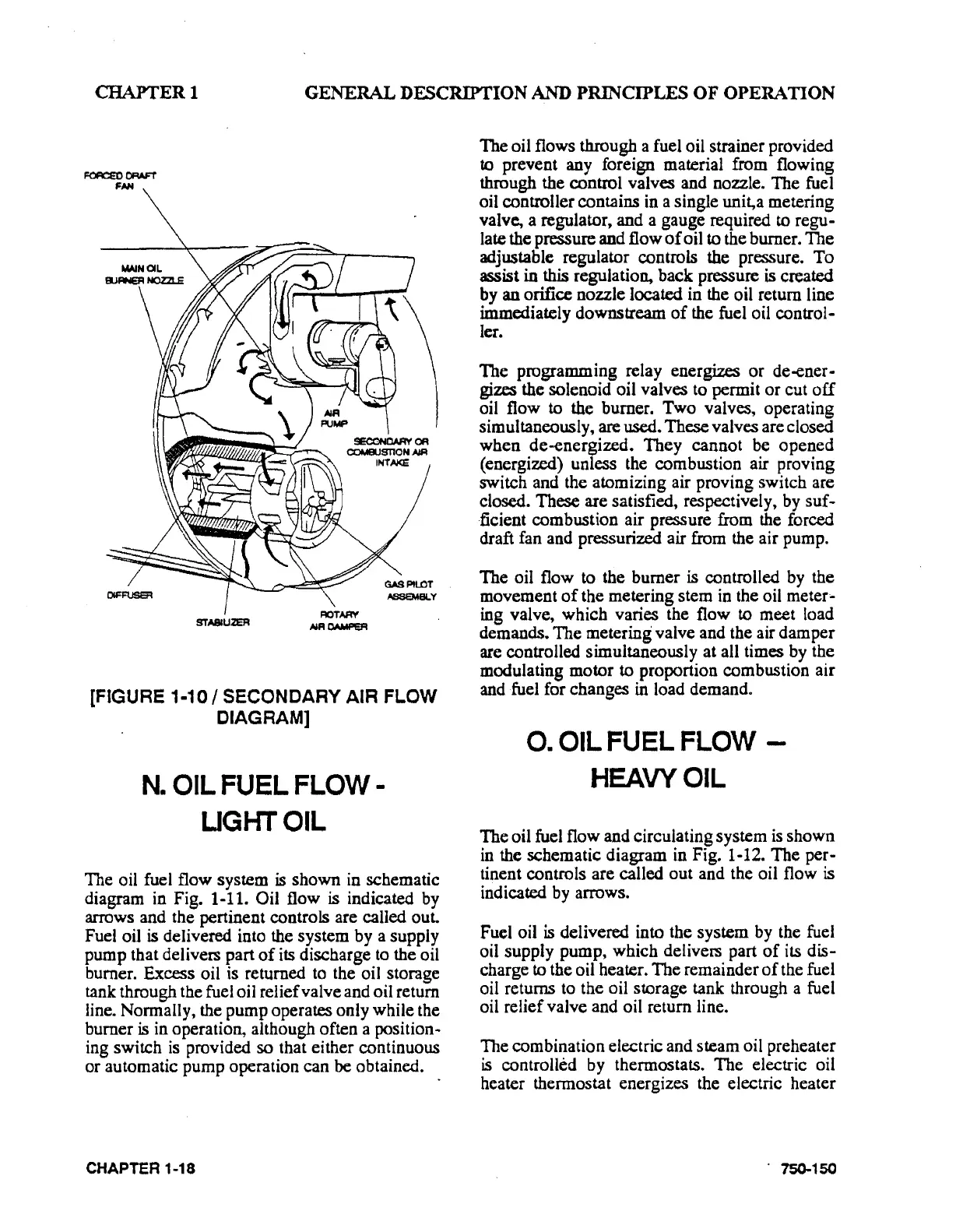
[FIGURE
1·1
0 I SECONDARY AIR FLOW
CIA
GRAM]
N.
OIL FUEL
FLOW-
UGI-ITOIL
The oil fuel flow system is shown in schematic
diagram in Fig. 1-11.
Oil flow is indicated by
arrows and the pertinent controls are called out.
Fuel oil
is
delivered into the system by a supply
pump that delivers part
of
its
discharge
to
the oil
burner. Excess oil
is
returned
to
the oil storage
tank through the fuel oil relief valve and oil return
line. Normally, the pump operates only while the
burner
is
in operation, although often a position-
ing switch
is
provided so that either continuous
or automatic pump operation can
be
obtained.
CHAPTER 1-18
The oil flows through a fuel oil strainer provided
to
prevent any foreign material from flowing
through the control valves and nozzle. The fuel
oil controller contains in a single unit,a metering
valve, a regulator, and a gauge required
to
regu-
late the pressure and flow
of
oil to the burner. The
adjustable regulator controls the pressure. To
assist
in this regulation, back pressure
is
created
by an orifice nozzle located in the oil return line
immediately downstream
of
the fuel oil control-
ler.
The programming relay energizes or
de-ener-
gizes the solenoid oil valves to permit or cut
off
oil flow to the burner. Two valves, operating
simultaneously, are used. These valves are closed
when de-energized. They cannot be opened
(energized) unless the combustion air proving
switch and the atomizing air proving switch are
closed.
These are satisfied, respectively,
by
suf-
·ficient combustion air pressure from the forced
draft fan and pressurized air from the air pump.
The oil flow
to
the burner is controlled
by
the
movement
of
the metering stem
in
the oil meter•
ing valve, which varies the flow to meet load
demands. The metering valve and the air dam per
are controlled simultaneously at all times
by
the
modulating motor to proportion combustion air
and fuel for changes
in
load demand.
0.
OIL FUEL FLOW -
HEAVY
OIL
The oil fuel flow and circulating system
is
shown
in the schematic diagram in Fig. 1-12. The
per-
tinent controls are called out and the oil flow
is
indicated
by
arrows.
Fuel oil
is delivered into the system by the fuel
oil supply pump, which delivers part
of
its dis-
charge to the oil heater. The remainder
of
the fuel
oil returns
to
the oil storage tank through a fuel
oil relief valve and oil return line.
The combination electric and steam oil preheater
is
controlled by thermostats. The electric oil
heater thermostat energizes the electric heater
. 750-150