CHAPTERS
L
v
-~
/
w
3
L
,
u..
/
;::;
N
v
0
0
/
/
~
w
/"'
0
a:
/
w
a.
/
v
,
9 8 7 6
54
3 2
-
PERCENT
02
IN
FLUE
GAS
60 50 40 30 20 10
PERCENT
EXCESS
AIR
12
-"'
1'1
'\
1\
10
'
9
8
7
6
5
0
ADJUSTMENT
PROCEDURES
I
I
!...
'
'"
\
I
""'
'
I
i\
I
\
I
'
I
1\
I
I
\
I
I
\:
~
2 3 4 5 6
PERCENT
CO---
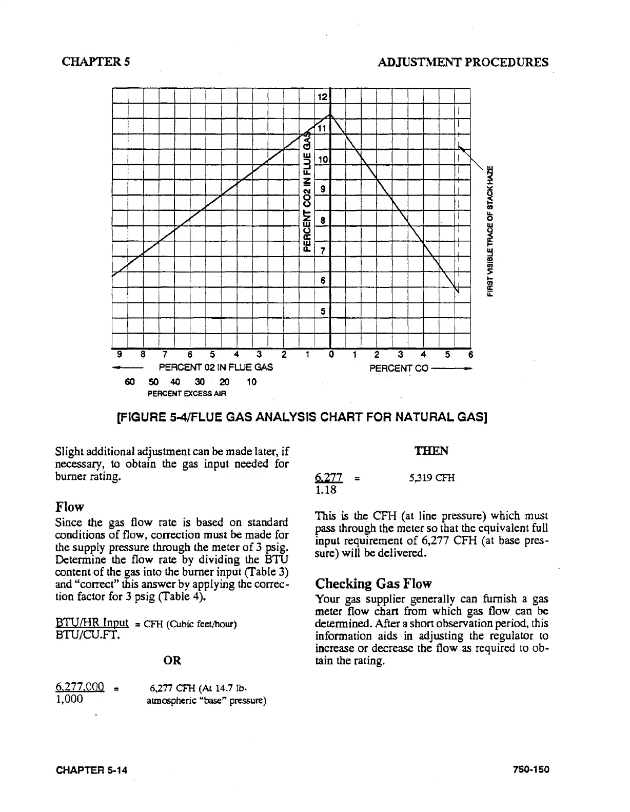
[FIGURE 5-4/FLUE GAS ANALYSIS CHART FOR NATURAL GAS]
Slight additional adjustment can be made later,
if
necessary,
to
obtain the gas input needed for
burner rating.
Flow
Since the gas flow rate
is
based
on
standard
conditions
of
flow, correction must be made for
the supply pressure through the meter
of
3 psi
g.
Determine the flow rate by dividing the BTU
content
of
the gas into the burner input (Table 3)
and "correct" this answer by applying the correc-
tion factor for 3 psig (Table 4).
BTUIHR Input = CFH (Cubic feet/hour)
BTU/CU.Fr.
6.277.000
::
1,000
CHAPTER 5-14
OR
6)."n
CFH (A114.7 lb·
atmcspheric "base" pressure)
Q;]JJ_
::
1.18
THEN
5,319 CFH
This
is
the
CFH
(at line pressure) which
must
pass through the meter so that the equivalent full
input requirement
of
6,277 CFH (at base pres-
sure) will be delivered.
Checking
Gas
Flow
Your gas supplier generally can furnish a gas
meter flow chart from which gas flow can be
determined. After a short observation period, this
information aids
in
adjusting the regulator
to
increase
or
decrease the flow
as
required
to
ob-
tain the rating.
750
..
150