CHAPTERS
Final adjustment
of
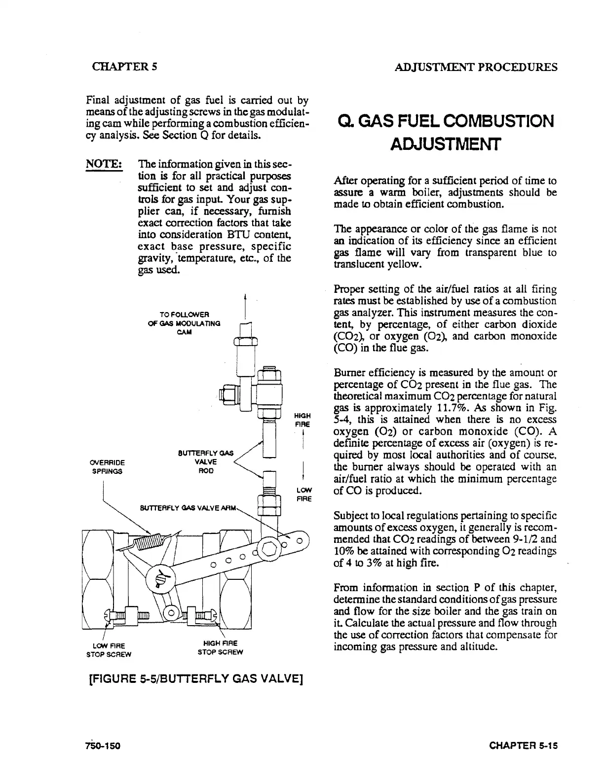
gas fuel is carried out by
means
of
the adjusting screws
in
the gas modulat-
ing
cam
while performing a combustion efficien-
cy
analysis. See Section Q for details.
NOTE:
The
information given
in
this
sec-
tion is for all practical purposes
sufficient to set and adjust
con-
trols for gas input.
Your
gas
sup·
plier can,
if
necessary, furnish
exact correction factors that take
into consideration
BTU
content,
exact
base
pressure,
specific
gravity, ·temperature, etc.,
of
the
gas
used.
OVERRIDE
SPRINGS
LON ARE
STOP
SCREW
TOFOUONER
OF
GAS
MOOULA
TING
CAM
HIGH
ARE
STOP
SCREW
HIGH
ARE
t
!
LON
ARE
[FIGURE 5-5/BUTTERFLY GAS VALVE]
1So..1so
ADJUSTMrnNTPROCEDURES
Q.
GAS
FUEL
COMBUSTION
ADJUSTMENT
After operating for a sufficient period
of
time
to
assure a warm boiler, adjustments should be
made
to obtain efficient combustion.
The
appearance
or
color
of
the gas flame
is
not
an indication
of
its
efficiency since an efficient
gas
flame will vary from transparent blue
to
translucent yellow.
Proper setting
of
the air/fuel ratios at all firing
rates must be established by use
of
a combustion
gas analyzer. This instrument measures the
con-
tent, by percentage,
of
either carbon dioxide
(COz),
or
oxygen (Oz), and carbon monoxide
(CO) in the flue gas.
Burner efficiency is measured by the amount
or
percentage
of
C02
present in the flue gas. The
theoretical maximum
C02
percentage for natural
gas is approximately 11.7%.
As
shown
in Fig.
S-4, this
is
attained when there is no excess
oxygen
(02)
or
carbon
monoxide
(CO). A
definite percentage
of
excess air (oxygen)
is
re·
quired by most local authorities and
of
course,
the burner always should be operated with an
air/fuel ratio at which the minimum percentage
of
CO is produced.
Subject
to local regulations pertaining
to
specific
amounts
of
excess oxygen, it generally is recom-
mended that
C02
readings
of
between 9-1/2 and
10% be attained with corresponding Oz readings
of
4 to
3%
at high fire.
From information
in
section P
of
this chapter,
detennine the standard conditions
of
gas pressure
and flow for the size boiler and the gas train on
it. Calculate the actual pressure and flow through
the use
of
correction factors that compensate for
incoming gas pressure and altitude.
CHAPTER 5-15