CHAPTERS
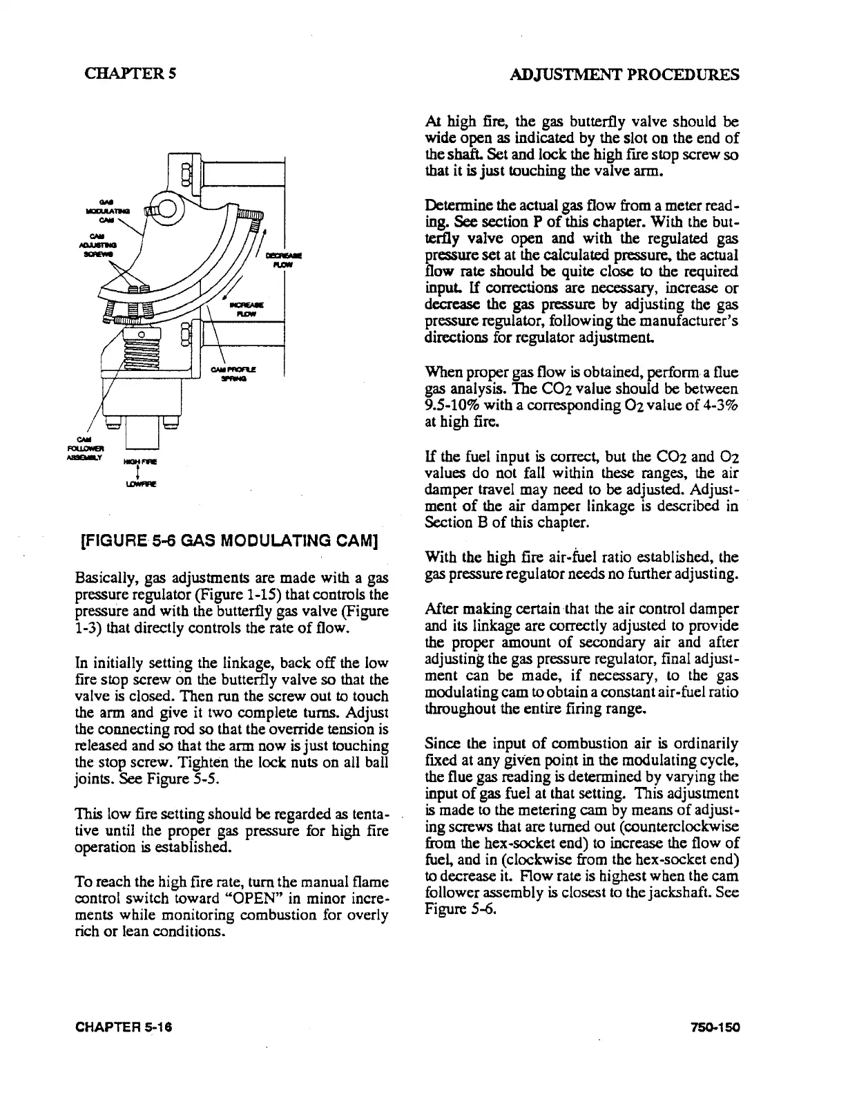
(FIGURE· 5-6 GAS MODULATING CAM]
Basically, gas adjustments are made with a gas
pressure regulator (Figure 1-15) that controls the
pressure and with the butterfly gas valve (Figure
1-3) that directly controls the rate
of
flow.
In initially
setti~g
the linkage, back
off
the low
fire
stop
screw
on
the butterfly valve
so
that the
valve
is
closed.
Then
run the screw
out
to
touch
the arm and give it two complete turns. Adjust
the connecting
rod
so
that the override tension is
released and
so
that the arm
now
is
just
touching
the stop screw. Tighten the lock nuts
on
all ball
joints.
See Figure S-5.
This low fire setting should be regarded as tenta-
tive until the proper gas pressure for high fire
operation
is
established.
To
reach the high fire rate,
tum
the manual flame
rontrol switch toward
"OPEN"
in minor incre-
ments while monitoring combustion for overly
rich
or
lean conditions.
CHAPTER 5-16
ADJUSTMENT PROCEDURES
At
high fire, the gas butterfly valve should
be
wide
open
as indicated by the
slot
on
the end
of
the shaft.
Set
and lock the high
fue
stop screw
so
that it is
just
touching the valve arm.
Determine the actual gas flow from a meter read-
ing.
See section P
of
this chapter. With the but-
terfly
valve
open
and
with
the regulated gas
pressure
set
at the calculated
pressu~
the actual
flow rate should
be
quite close to the required
input.
If
corrections are necessary, increase
or
decrease the gas pressure by adjusting the gas
pressure regulator, following the manufacturer's
directions for regulator adjustment.
When proper gas flow
is
obtained, perform. a flue
gas analysis.
The
C02
value should be between
9.5-10% with a corresponding
02
value
of
4-3%
at high fire.
If
the fuel input
is
correct, but the
C02
and
02
values
do
not fall within these ranges, the air
damper travel may need to be adjusted. Adjust-
ment
of
the air
damper
linkage
is
described in ·
Section B
of
this chapter.
With the high fire
air-fuel ratio established, the
gas
pressure regulator needs no further adjusting.
After making certain
·that the air control
damper
and its linkage are correctly adjusted to provide
the proper amount
of
secondary air and after
adjusting the gas pressure regulator, final adjust-
ment
can
be
made,
if
necessary, to the gas
modulating cam to obtain a constant air-fuel ratio
throughout the entire firing range.
Since the input
of
combustion air
is
ordinarily
ftxed at any
given poiQt in the modulating cycle,
the flue gas reading
is
determined by varying the
input
of
gas fuel at that setting. This adjustment
is
made to the metering
cam
by means
of
adjust-
ing screws that are turned
out
(counterclockwise
from the hex-socket end) to increase the flow
of
fue~
and in (clockwise from the hex-socket end)
to decrease it. Flow rate is highest when the cam
follower assembly
is
closest to the jack:shaft. See
Figure
S--6.
75().150