CHAPTER2
THE
PRESSURE VESSEL
8cH..,
Boner
System
T..,pe,.ture
Crap-
De9,... F
S!a
Ou•t
10 1
20
30
I
40 50
10
70
"'
10
100
{1000)
(BHP)
Btu/Hr
Muimum =n:uiattnv Rllte - GPM
15
500
100 1
50
33
25
20
17
,.
12
11
10
20 670
13-4
I
61
•s
33
27
221
19
11
1
15
13
30
1.005
2001
100
67
50
4&0j
33
29
251
22
20
4&0
1,340
25a
I
13-4
89
61
I
So4l
45
38
33
30
27
so
1,675
3351
HS8
I
112 1
&4
67
sol
.aj
42 I 37
33
60
2.010
4021
201
134
101
!
sol
67
sa
sol
45
40
70
2.34!
•1o
1
235j
157 1
11e I
941
1a
1
57
s9
1
52
47
80 2.580
5361
2sa
1
179 1
134
I
101 1
901
nj
stl
60
5:4
100
3..150
I
67o 1
3351
223
168
13-4
,2,
961
841
75 1
67
125
•.18.5 I
8361
-'18 1
2791
209
I
168 I 1.-o I 120 I
1os
I
931
&4
150
s.02S
1
1.oos
I
503
335j
251
201 1
1sa
1
,...,.
1 126
112
1 100
200
I
6.695
1.340
I
67o 1
4o&7
335
I
268
I
22•
I 192 I 168 I
1•e
I 134
2SO
a.370 1 1
.s1s
I
8381
ssal
<419
I
3351280
24&0
1 210 1 186
167
I
300
'
1o,045 \ 2.o1o 1 ,
.oos
I
67o I
S03
I
402 I
ns
I 2a1 I
251
I 223 I
201
3SO
11.120 1 2..35o 1
1.11s
1
78A
I
587
·I
•10
I
392
I
338
294 I
251
2:35
40)
I
13,AOO
I 2.680 I 1.340 I
895 610
535 I
~7
I
383
33512981258
5CXl
16.740 1 3.350 1
1.67s
1 1.120
838
I
670 !
ssa
I
•79
I
•1e
I 312
33.5
600
. 20.080
•.020
I
2..01
o
1,340 ' 1.005
sos
! 67o I 575 r
sa2
I
4.&8
4.02
700 23.430
•.aso
I
2..3<45
1.565 1
1.
175
I
s.o
1
1a.s
1 67o I
sas
.520 1 47o
800
26.780
s.3eo
I 2.680
1,785
1.340
1.075
J 895 1
1ss
1
sto
595
S3S
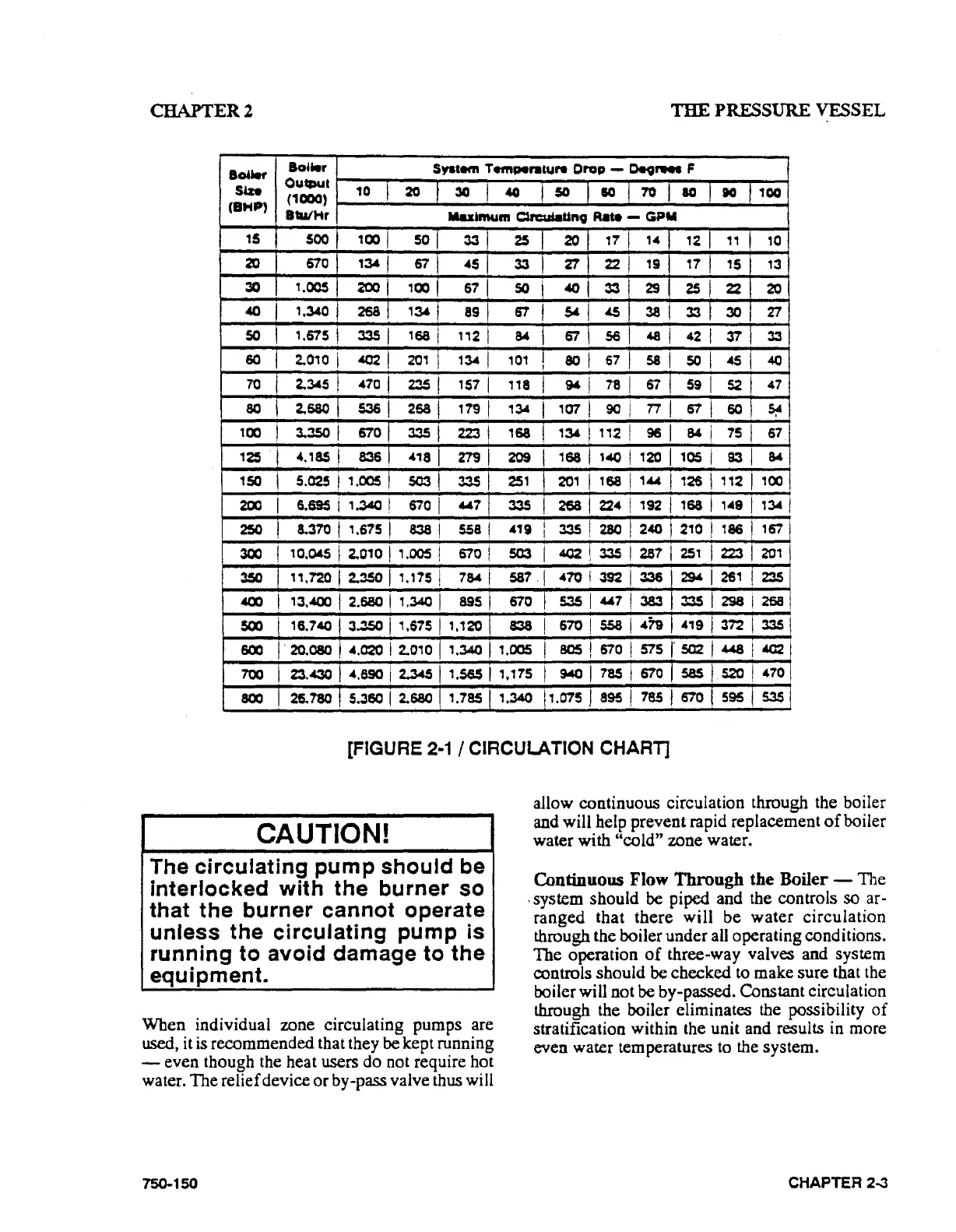
[FIGURE
2·1
I CIRCULATION CHART]
CAUTION!
The
circulating
pump
should
be
interlocked
with
the
burner
so
that
the
burner
cannot
operate
unless
the
circulating
pump
is
running
to
avoid
damage
to
the
equipment.
When
individual zone circulating
pumps
are
used, it is
recommended
that they
be
kept running
-
even
though the heat users
do
not require hot
water.
The
relief device
or
by-pass valve thus will
750-150
allow continuous circulation through the boiler
and will help prevent rapid replacement
of
boiler
water
with
"cold"
zone water.
Continuous Flow Through the Boiler - The
. system
should
be
piped and the controls so ar-
ranged
that
there
will
be
water
circulation
through the boiler
under
all operating conditions.
The
operation
of
three-way valves and system
controls
should
be
checked
to make
sure
that the
boiler will not
be
by-passed. Constant circulation
through the boiler eliminates the possibility
of
stratification within the unit and results in more
even
water temperatures to the system.
CHAPTER
2...3