CB FALCON
113 750-265
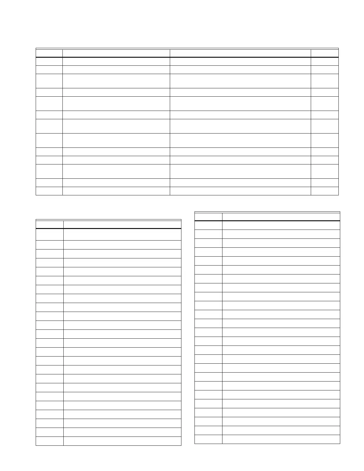
239 Invalid S2 (J8-6) connector type setting L
240 Invalid S5 (J8-11) connector type setting L
241 Exchanger sensor not allowed with stack
connector setting
L
242 Invalid DHW auto detect configuration L
243 Invalid UV with spark interference not
compatible with Ignitor on throughout PFEP
L
244 Internal fault: Safety relay test invalid state L
245 Invalid Outlet connector type setting for T-
rise
L
246 4-20mA cannot be used for both modulation
and setpoint control
L
247 Invalid ILK bounce detection enable L
248 Invalid forced recycle interval L
249 STAT cannot be demand source when
Remote Stat is enabled
L
250 Invalid Fan speed error response L
251-255 RESERVED
Table 49. Falcon Lockout and Hold Codes. (Continued)
Code Description Recommended Troubleshooting of Lockout Codes NOTE
Table 50. Alerts.
Code Description
EE Management Faults
0 None (No alert)
1 Alert PCB was restored from factory defaults
2 Safety configuration parameters were restored
3 Configuration parameters were restored from
4 Invalid Factory Invisibility PCB was detected
5 Invalid Factory Range PCB was detected
6 Invalid range PCB record has been dropped
7 EEPROM lockout history was initialized
8 Switched application annunciation data blocks
9 Switched application configuration data blocks
10 Configuration was restored from factory defaults
11 Backup configuration settings was restored from
12 Annunciation configuration was restored from
13 Annunciation configuration was restored from
14 Safety group verification table was restored from
15 Safety group verification table was updated
16 Invalid Parameter PCB was detected
17 Invalid Range PCB was detected
System Parameter Errors
18 Alarm silence time exceeded maximum
19 Invalid safety group verification table was
20 Backdoor Password could not be determined.
21 Invalid safety group verification table was
22 CRC errors were found in application
23 Backup Alert PCB was restored from active one
24 RESERVED
25 Lead Lag operation switch was turned OFF
26 Lead Lag operation switch was turned ON
27 Safety processor was reset
28 Application processor was reset
29 Burner switch was turned OFF
30 Burner switch was turned ON
31 Program Module (PM) was inserted into socket
32 Program Module (PM) was removed from socket
33 Alert PCB was configured
34 Parameter PCB was configured
35 Range PCB was configured
36 Program Module (PM) incompatible with product
37 Program Module application parameter revision
38 Program Module safety parameter revision
39 PCB incompatible with product contained in
40 Parameter PCB in Program Module is too large
41 Range PCB in Program Module was too large for
42 Alert PCB in Program Module was too large for
43 IAS start check was forced on due to IAS
System Operation Faults
44 Low voltage was detected in safety processor
45 High line frequency occurred
Table 50. Alerts. (Continued)
Code Description