coM.sat ISDN Basic
created: page: file:
16/01/09 15 coMsat ISDN Basic Manual V2.7.doc
Note Protection Mark according to DIN 34!
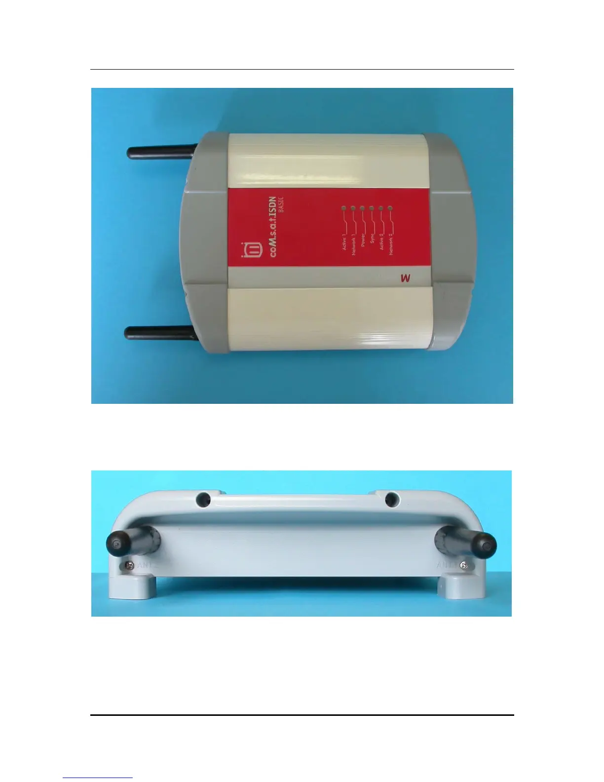
Figure 3: Top side of the coM.sat ISDN Basic
On the top side, there are the LED control indicators.
Figure 4: Rear side of the coM.sat ISDN Basic
On the rear side, there are the two RF- (SMA) connectors for the antennas, with
antennas screwed in.