coM.sat ISDN Basic
created: page: file:
16/01/09 79 coMsat ISDN Basic Manual V2.7.doc
Note Protection Mark according to DIN 34!
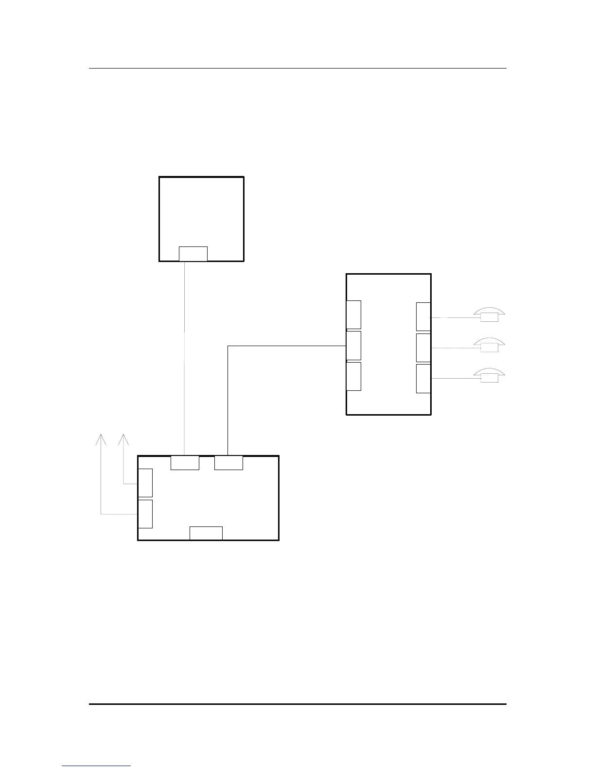
4.3 coM.sat ISDN Basic in router mode
To use the coM.sat ISDN Basic as router, the following connection schematic results.
This can vary depending on the TC system used, although the principle arrangement
is retained. The coM.sat ISDN Basic is installed as an exchange (NT) at the external
S0 bus and as TE at the ISDN network termination.
NT
PBX
NT
S0ext.
TE
TE
TE
TE
A1
A2
Aerials
S0ext.
S0ext.
co
M.s.a.t.
ISDN Basic
USB
Figure 36: Router Installation
The following figure shows the settings for a possible configuration.
Layer 3 must always be in NT mode and layer 2 and 1 are usually in NT mode, too.
These settings apply to the NT port of the device, while the TE port is always
configured in TE mode on all layers. The synchronisation is carried out via the TE
port.
In this mode the green LEDs function as in NT mode, i.e. if they are permanently lit,
this shows that the GSM channels are logged in. If no call is being made then the
yellow LEDs are off. While a connection is being set up, the yellow LEDs flash slowly.