InteliLite4 AMF20 Global Guide
598
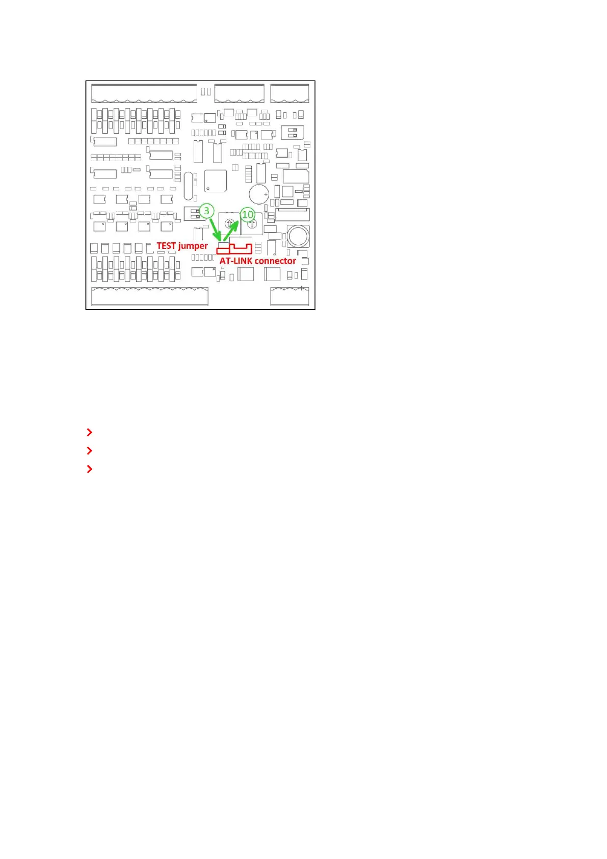
4. Connect the unit with PC via RS232-null modem cable and AT-Link conv
5. Connect power supply of the module (status LED lights continuously)
6. Launch FlashPgr.exe PC software (version 4.2 or higher)
7. In FlashPrg program choose card Inteli IO8/8 and load FW for the module
8. Set the proper COM port (connected with the unit) and press the Start button
9. Wait till process is done (if the process does not start – after 60 seconds the "Timeout" will be evaluated).
In this case please check:
You have proper connection with the unit
COM port selection is correct
Module has power supply, (no CAN bus connection, status LED lights continuously)
10. After successful programming disconnect AT-Link conv , remove TEST jumper and disconnect power
supply
11. Connect power supply again (status LED should blink)
12. Module FW is upgraded
LED indication
Binary input
Each binary input has an LED which indicates input signal. LED is shining when input signal is set, and LED is
dark while input signal has other state.
Binary output
Each binary output has an LED which indicates output signal. Binary output LED is shining when binary
output is set. When this LED is shining, then the module is configured as 8 binary inputs and 8 binary outputs.
When this LED is dark, the module is configured as 16 binary inputs.
LEDat power connector – status LED