InteliLite4 AMF20 Global Guide
599
LEDstatus Description
Dark FW in module does not work correctly.
Flashing Module does not communicate with controller (in case non-zero CAN address).
Lights
Power supply is in the range and the communication between Inteli IO8/8 and controller
works properly.
Or power supply is in range and zero CAN address is set. (in case zero CAN address
module doesn’t communicate with the controller).
Wiring
The following diagrams show the correct connection of inputs and outputs.
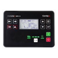
Binary inputs – pull up
There are two options of wiring. On upper picture you can see example of binary input is connected between
BIN2 and COM (COM is connected internally to the GND (-) – dashed line).
In lower picture is an example of wiring between BIN2 and GND (-). Both ways are correct.
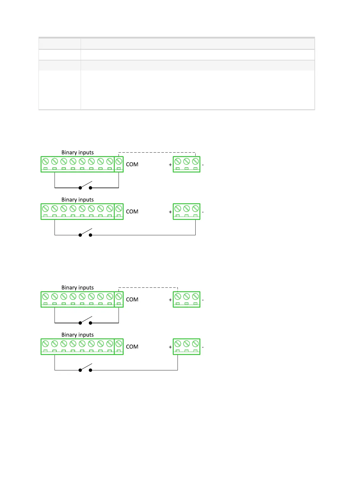
Binary inputs – pull down
There are two options of wiring. In the upper picture you can see an example of binary input connected
between BIN2 and COM (COM is connected internally to the Ucc (+) – dashed line).
In the lower picture is an example of wiring between BIN2 and Ucc (+). Both ways are correct.